Snap acting split flapper valve

a flapper valve and split-type technology, applied in the direction of functional valve types, separation processes, transportation and packaging, etc., can solve the problems of inability to meet the system air flow requirements, not being regularly serviced, and insufficient airflow through the system

Inactive Publication Date: 2007-12-25
HONEYWELL INT INC
View PDF35 Cites 42 Cited by
  • Summary
  • Abstract
  • Description
  • Claims
  • Application Information

AI Technical Summary

Problems solved by technology

In these situations, the cabin air filtration system may be unable to meet the system air flow requirements.
In some instances, the air filter is an optional component of the system, so it may not be regularly serviced.
Should the air filter become obstructed, it may not be noticed that there is inadequate airflow through the system.
And even if it is noticed, there may not be time or resources to clean or replace the air filter, especially during flight.

Method used


Image

  • Snap acting split flapper valve
  • Snap acting split flapper valve
  • Snap acting split flapper valve

Examples


Embodiment Construction

[0014]The following detailed description of the invention is merely exemplary in nature and is not intended to limit the invention or the application and uses of the invention. Furthermore, there is no intention to be bound by any theory presented in the preceding background of the invention or the following detailed description of the invention.

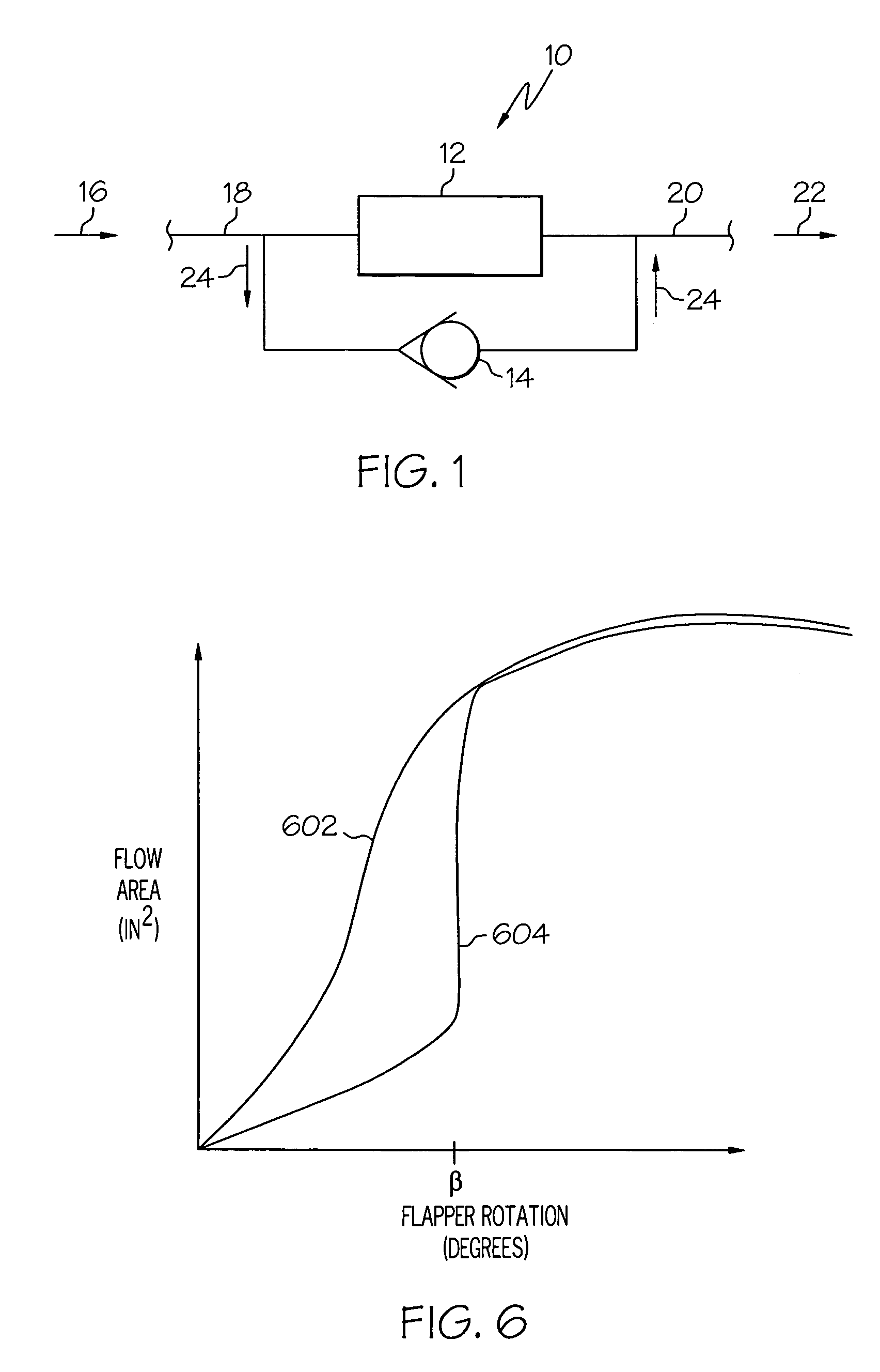
[0015]FIG. 1 is a simplified schematic diagram illustrating a portion of an aircraft cabin air filtration system 10 that includes an air filter 12 and a filter bypass valve 14 positioned in parallel between an inlet duct 18 and an outlet duct 20. During normal operation, air is filtered through air filter 12 at an air flow rate that meets predetermined air flow requirements of system 10. Filter bypass valve 14 is movable between a closed position, in which no air flows through the filter bypass valve 14, and an open position, in which air flows through the filter bypass valve 14. The bypass valve 14 is configured to be in the closed position...


PUM

PropertyMeasurementUnit
pressureaaaaaaaaaa
differential pressure magnitudeaaaaaaaaaa
cross sectional flow areaaaaaaaaaaa

Abstract

A filter bypass valve is disposed in parallel with an aircraft cabin air filtration system air filter. During normal operation, air is filtered through the air filter at an air flow that meets air flow requirements of the system. The bypass valve is designed to remain closed during normal use, and to open if the differential pressure across the air filter reaches a predetermined opening differential pressure to allow airflow to be partially or fully diverted around the air filter.

Description

TECHNICAL FIELD[0001]The present invention relates generally to aircraft cabin air filtration system, and more particularly to a split flapper valve that bypasses air to flow around an air filter in the system in the event the air filter is unable to meet the system air flow requirements.BACKGROUND[0002]Many aircraft use an aircraft cabin air filtration system to clean the cabin air. These systems usually include an air filter, such as a hepa-filter, that cleans the air but may become obstructed during use, thereby providing reduced airflow. In these situations, the cabin air filtration system may be unable to meet the system air flow requirements. In some instances, the air filter is an optional component of the system, so it may not be regularly serviced. Should the air filter become obstructed, it may not be noticed that there is inadequate airflow through the system. And even if it is noticed, there may not be time or resources to clean or replace the air filter, especially duri...

Claims


Application Information

Patent Timeline
Patent Type & Authority Patents(United States)
IPC IPC(8): B01D46/00F16K17/00
CPCF16K15/038Y10T137/7839Y10T137/7845Y10T137/7898
Inventor WILLIAMS, MARK W.SLEEPER, ROBERT D.ATKINS, DON J.DENIKE, STUART K.
Owner HONEYWELL INT INC
Why Eureka
Try Eureka