Flip-up convex mirror attachment

a convex mirror and mirror technology, applied in the direction of mirrors, mountings, instruments, etc., can solve the problems of product defects, inconvenience to the vehicle owner in additional costs, loss of specialty features, etc., and achieve the effect of easy attachment, easy and quick movement, and increasing the width of the reflected imag

Inactive Publication Date: 2008-01-08
ROOSE ALISON L
View PDF16 Cites 126 Cited by
  • Summary
  • Abstract
  • Description
  • Claims
  • Application Information

AI Technical Summary

Benefits of technology

[0013]The Flip-Up Convex Mirror Attachment solves these problems by providing a convex mirror that can be easily attached to the original equipment mirror and easily and quickly moved between the in-use and non-use positions by the vehicle operator based on needs and driving preferences.
[0014]The Flip-Up Convex Mirror Attachment offsets the convex mirror to eliminate the vehicle operator seeing their reflected image in the convex mirror. A wedge block is attached to the OEM mirror surface and has a predefined angle to offset the convex mirror to ensure the convex mirror reflects an image to the rear of the vehicle in the same horizontal plane as the normal mirror while greatly increasing the width of the reflected image.
[0015]Furthermore, the wedge block ensures a consistent view towards the rear of the vehicle is maintained of the same reflected image in both the flip-up convex mirror and OEM mirror on the side of the mirror closest to the driver. By maintaining this common reference point, the vehicle operator can safely transition between the convex and normal reflected images and utilize the mirror in the position that best serves the driving needs at any point in time.
[0016]Furthermore, the attachment between the wedge block and the back of the convex mirror may include a rotatable slide mechanism that allows the convex mirror to be hinged about the horizontal surface anywhere along the circumference of the convex mirror. This rotatable sliding mechanism allows the operator to make minor adjustments in the reflected point on the driver's side of the convex mirror to compensate for variations in vehicle designs, vehicle width, and driver placement relative to the interior rear view mirror.

Problems solved by technology

However, the NHTSA has not adopted changes in the motor vehicle standards to allow for customer delivery of a motor vehicle with an interior convex mirror.
This is an inconvenience to the vehicle owner in additional costs and loss of functionality of specialty features now common in OEM mirrors and mirror frames.
While some manufacturers have attempted to solve the problem of inadequate driver visibility from the interior rear view mirror by combining a flat mirror and a convex mirror, these products are defective because they replace the original equipment mirror or prevent the OEM flat mirror from being used by the driver.
While this device may be useful, it is inadequate for attaching to the original equipment mirror and forces the consumer to replace the entire mirror assembly and forego the specialty features available in the OEM mirror assembly.
Its use is also limited to vehicles with a left-side driver.

Method used


Image

  • Flip-up convex mirror attachment
  • Flip-up convex mirror attachment
  • Flip-up convex mirror attachment

Examples


Embodiment Construction

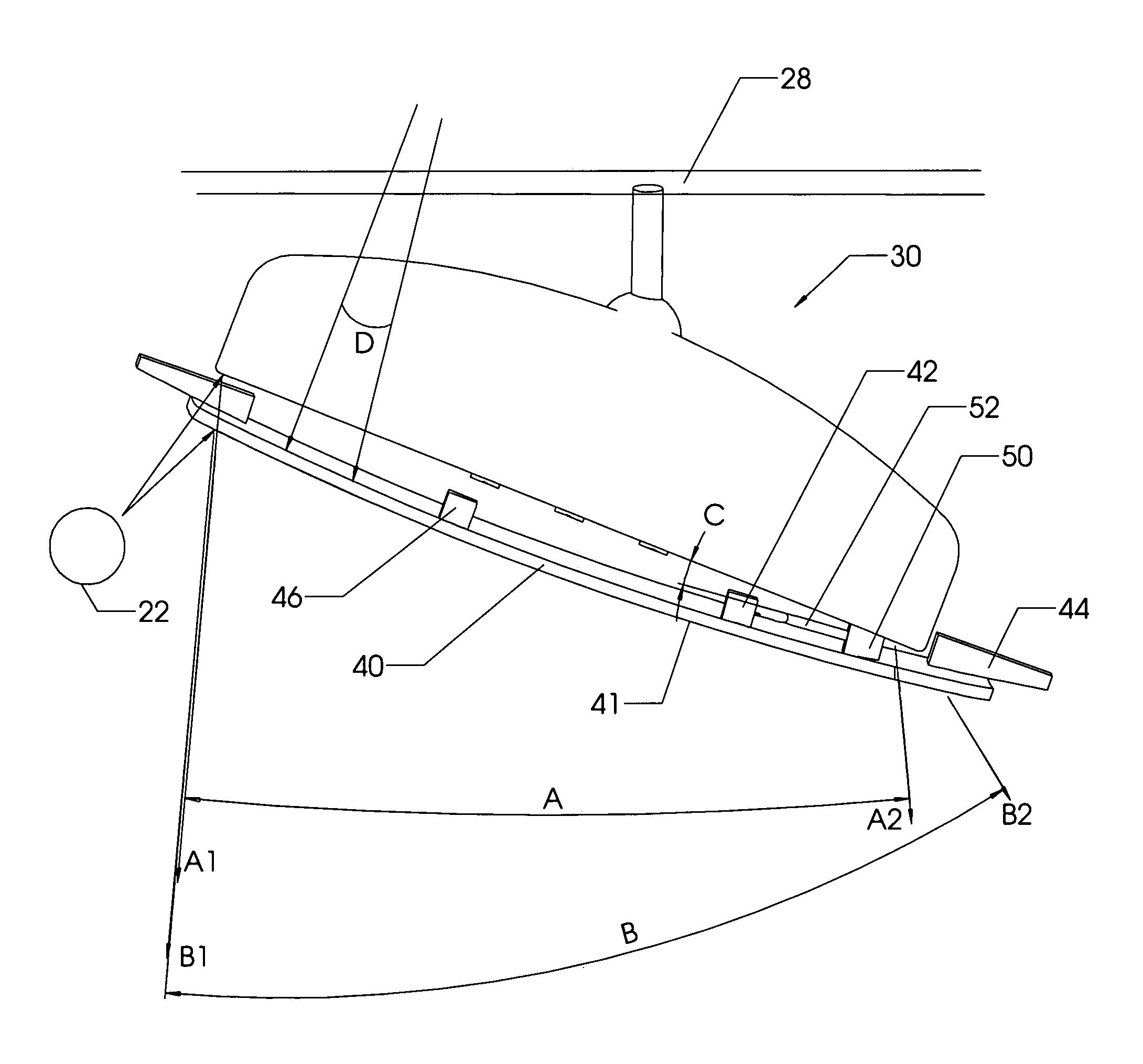
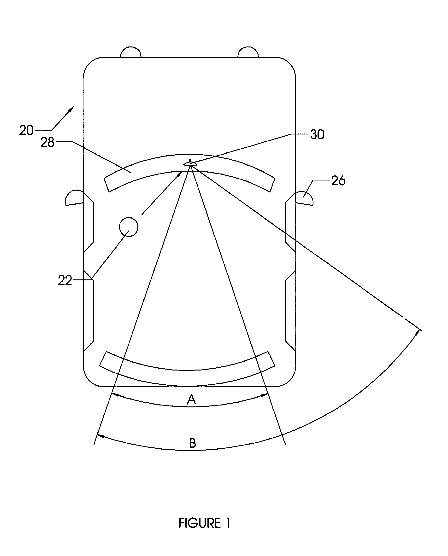
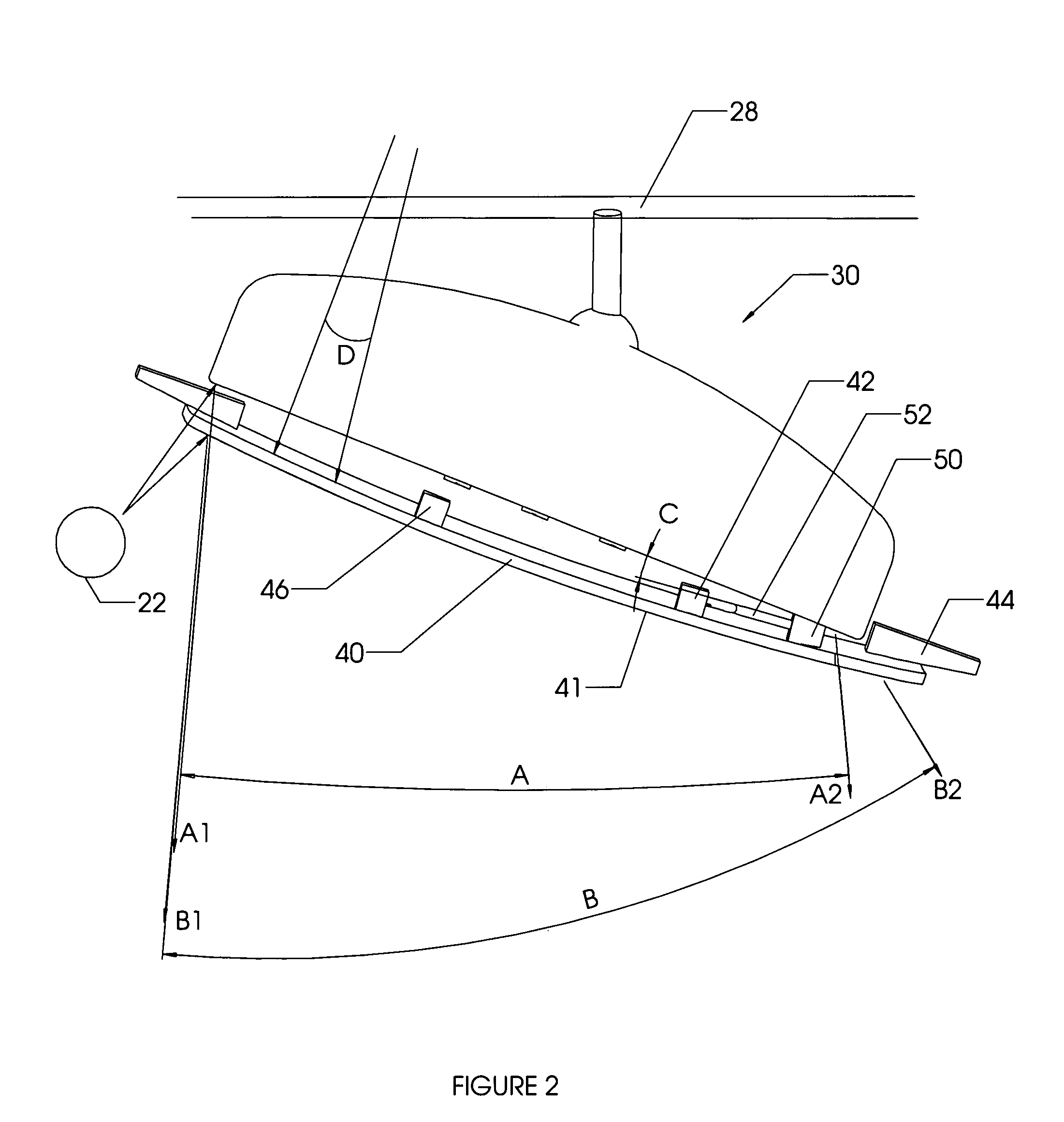
[0027]FIG. 1 illustrates an automotive vehicle 20 having a conventional flat rear view mirror and a flip-up convex mirror attachment 30 and further illustrating the rear view viewing angle available from the driver's perspective using either mirror. As shown in this illustration, the driver of the vehicle 22 would have a rearward view represented by angle A when using the conventional flat original equipment manufacturer (OEM) mirror. A wider-angle rearward view represented by angle B is possible when using the flip-up convex mirror attachment with the convex mirror placed in the DOWN or in-use position. This wide-angle view B would reflect images to the driver where objects would be closer than they appear; but the driver 22 is accustomed to this perspective and appreciates the wide-angle view B to gain visibility of vehicles and other objects adjacent to their vehicle without the need to significantly rotate their head to utilize the passenger side mirror 26.

[0028]By providing a w...


PUM


Abstract

A flip-up convex mirror attachment for installation onto the original equipment mirror in vehicles with either a left-side or right-side driver. The flip-up convex mirror attachment attaches to the mirror surface of the original equipment interior mirror found in most motor vehicles. The flip-up convex mirror attachment contains an angled hinge block for creating a predefined offset angle between the flip-up convex mirror and the OEM mirror such that the reflected image on the side of the mirror nearest the driver is maintained at generally the same point behind the vehicle as the original equipment mirror. The wedge-based hinge assembly may be attached to the flat mirror surface on either a left-side or right-side driver vehicle and still maintain the desired angular offset between the OEM and flip-up convex mirrors.

Description

CROSS-REFERENCES TO RELATED APPLICATIONS[0001]This application claims prior art from U.S. Provisional Patent application No. 60 / 710,851 filed Aug. 24, 2005 by Alison L. Roose entitled FLIP-UP CONVEX MIRROR ATTACHMENT the entirety of which is hereby incorporated by reference.FIELD OF INVENTION[0002]The present invention relates to an apparatus for a flip-up convex mirror for attachment to a motor vehicle's original equipment manufacturer (OEM) interior rear view mirror. The flip-up convex mirror attachment apparatus further provides a means for maintaining one side of the reflected image constant as the OEM mirror or flip-up convex mirrors are used without the need for the driver to adjust the mirror assembly. The apparatus further provides a means for the convex mirror to be easily operated and positioned into either the down or up position; thereby allowing the driver to select the desired reflected view based upon the driving situation and to utilize the custom features that are n...

Claims


Application Information

Patent Timeline
Patent Type & Authority Patents(United States)
IPC IPC(8): G02B5/08G02B7/18
CPCB60R1/08
Inventor ROOSE, ALISON L.
Owner ROOSE ALISON L
Why Eureka
Try Eureka