Auxiliary device for engine spark plug ignition

a technology of spark plug ignition and auxiliary device, which is applied in the direction of electric ignition installation, machines/engines, mechanical equipment, etc., can solve the problems of reducing the sparkplug voltage, disturbing the waveform, and unnecessary mechanical power distribution using a distributor, and achieves high-efficiency sparkplug ignition, good high-voltage, and stable production

Inactive Publication Date: 2008-01-22
SUN AUTOMOBILE
View PDF3 Cites 0 Cited by
  • Summary
  • Abstract
  • Description
  • Claims
  • Application Information

AI Technical Summary

Benefits of technology

[0016]Because the auxiliary device for engine sparkplug ignition according to the present invention has the constitution described above, the following advantages are provided:
[0017](1) When the engine is running, back electromotive force generated on the primary coil side of the ignition coil is absorbed by the electrolytic capacitor and thereby suppressed, so that good high voltage can be stably produced on the second coil side, allowing for highly efficient sparkplug ignition.
[0018](2) As a result, ignition loss is limited, whereby engine output is improved.
[0019](3) Because combustion efficiency is improved in all speed ranges, torque drop off is alleviated, which improves acceleration response.
[0020](4) Consequently, engine fuel consumption is lowered and the harmful substance content of the exhaust gas is lowered.

Problems solved by technology

As such, mechanical power distribution using a distributor is unnecessary.
While the ignition energy is so large that the waveform in the arrow B interval is nearly vertical, this also disturbs the waveform.
Research by the present inventor has shown that the back electromotive force that occurs on the primary coil side influences the high-voltage generation on the secondary coil side and decreases the sparkplug voltage, which negatively impacts ignition efficiency.
In particular, when the engine is operating at high speed, the secondary coil side sparkplug voltage is unstable and a time lag occurs, which is highly likely to cause ignition loss (misfiring).

Method used


Image

  • Auxiliary device for engine spark plug ignition
  • Auxiliary device for engine spark plug ignition
  • Auxiliary device for engine spark plug ignition

Examples


Embodiment Construction

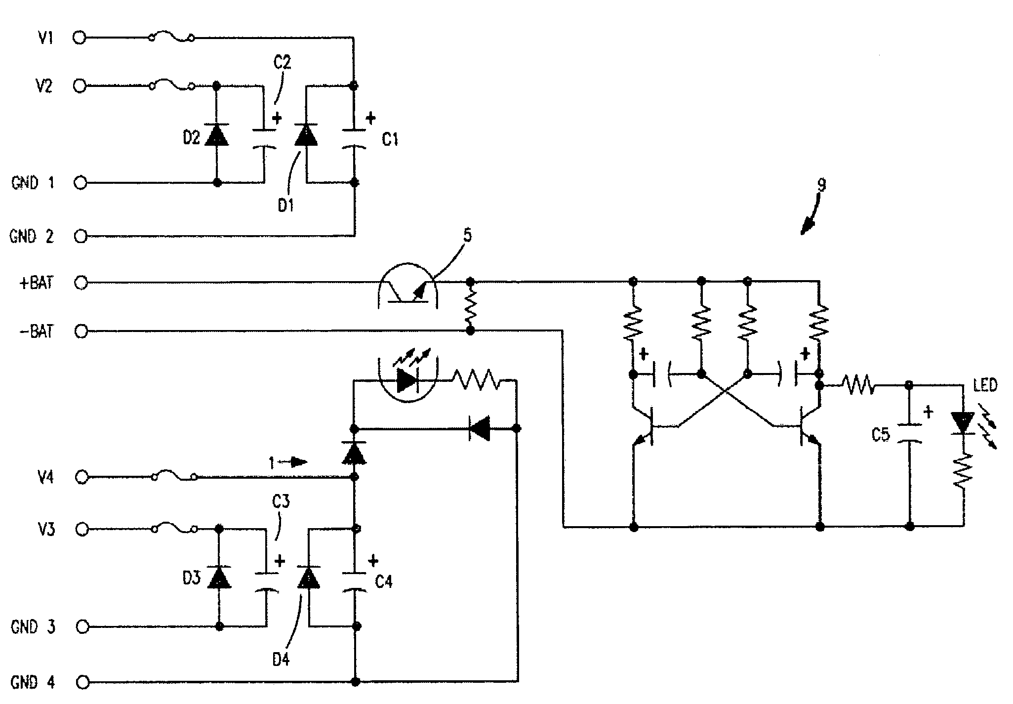
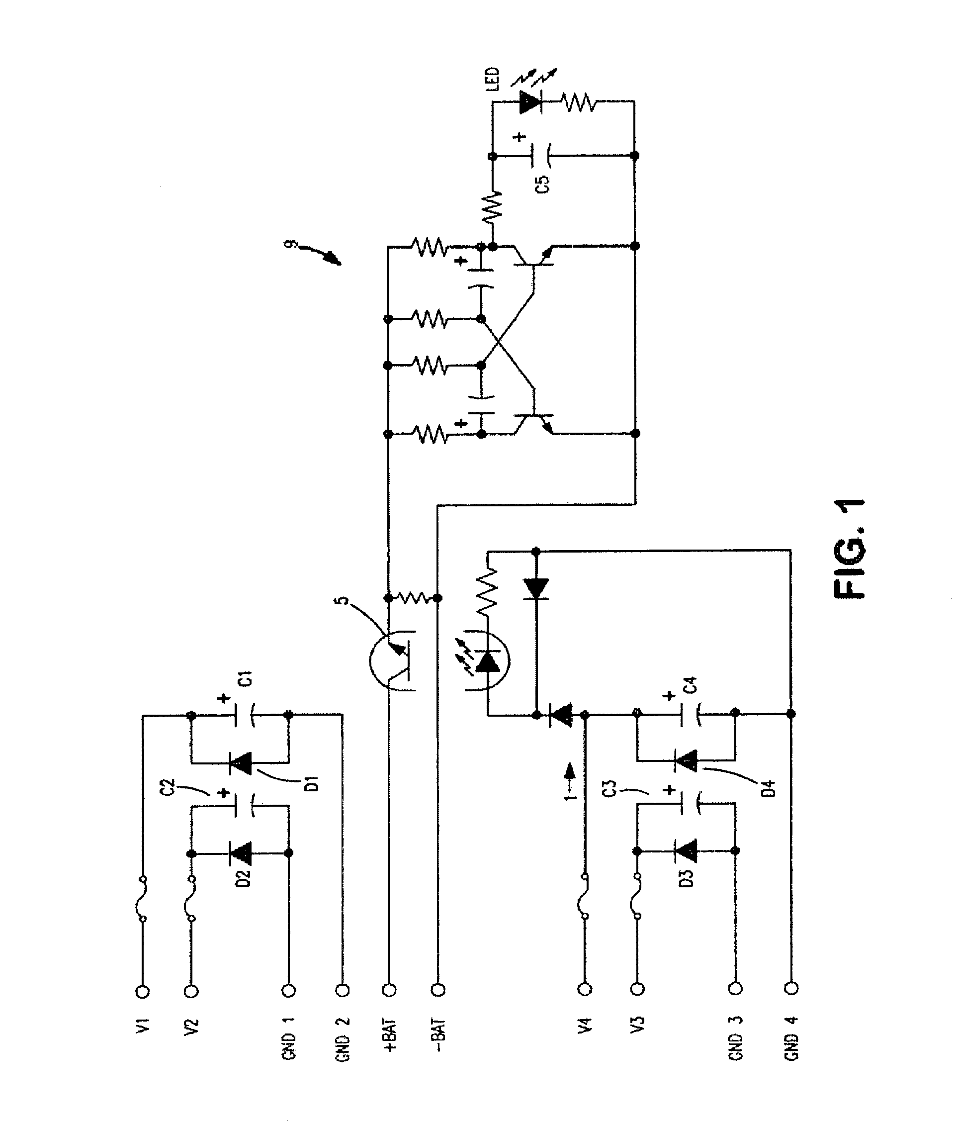
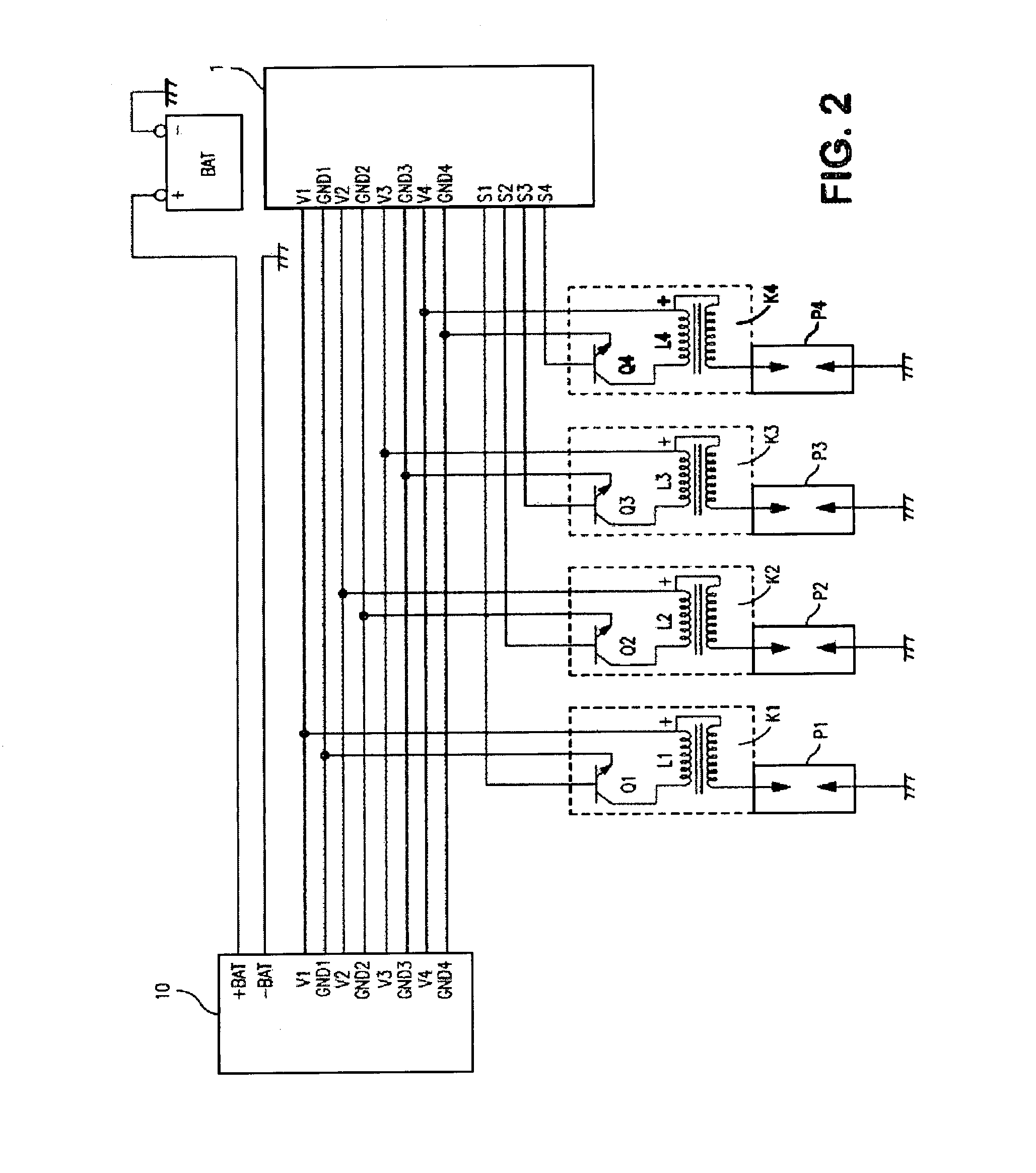
[0032]Modes of embodiment of the auxiliary device for engine sparkplug ignition according to the present invention will be described with reference to the drawings.

[0033]As shown in FIG. 1, FIG. 2 and FIG. 3, an auxiliary device for engine sparkplug ignition 10 comprises: electrolytic capacitors C1 to C4 connected in parallel between ground terminals GND 1 to GND 4 and positive terminals (V1 to V4 equals 12 V) of primary coils L1 to L4 of ignition coils K1 to K4, which are connected to sparkplugs P1 to P4 in a direct ignition system for a four-cylinder engine automobile; diodes D1 to D4 for preventing reverse current, which are connected in parallel in the reverse direction between the ground terminals GND 1 to GND 4 and the positive terminals on the primary coils L1 to L4 of the ignition coils K1 to K4; and a case 8, which houses the electrolyte capacitors C1 to C4 (having a capacitance of approximately 1400 μF) and the diodes D1 to D4, and which is fitted with a connector 6 for co...


PUM


Abstract

An auxiliary device for sparkplug ignition is provided having a case, and provided therein, electrolytic capacitors connected in parallel between ground terminals and positive terminals of the primary coils of the ignition coils, which are connected to sparkplugs in a direct ignition system. Diodes, which are connected in parallel, are provided in the reverse direction, between the ground terminals and the positive terminals on the primary coils. The case is fitted with a connector that connects to a dedicated harness. The back electromotive force generated in the primary side coils L1 to L4 of the ignition coils of each sparkplug is absorbed, so as to adjust the primary side current, allowing for generation of stabilized high voltage on the secondary coil side, and producing highly efficient sparkplug ignition.

Description

FIELD OF THE INVENTION[0001]The present invention relates to technology for supplying current at the time of sparkplug ignition, in an engine ignition system. In particular, an auxiliary device is provided for controlling engine spark plug ignition.BACKGROUND OF THE INVENTION[0002]Following the move to electronic control, in which gasoline engines are controlled by ECUs (electronic control units), automobile engine ignition systems are now full-transistor systems, in which mechanical points (contact breakers) are not needed, and more recently, there has been a move to ignition systems that do not need distributors, in which the power distribution function is based on mechanical operations, or high-voltage leads (secondary leads) with which energy loss is unavoidable.[0003]Direct ignition systems, which do not need distributors, are provided with a small independent ignition coil for each sparkplug, and ignition is performed by supplying low-voltage (equal to the battery voltage of 1...

Claims


Application Information

Patent Timeline
Patent Type & Authority Patents(United States)
IPC IPC(8): F02P15/00
CPCF02P3/0407F02P9/00F02D2400/11F02P3/0442F02P13/00
Inventor SUZUKI, JUN
Owner SUN AUTOMOBILE
Why Eureka
Try Eureka