
Automated belt cooking machine pancakes or the like

a belt cooking machine and automatic technology, applied in the field of automatic belt cooking machines for pancakes, can solve the problems of affecting the cooking process of the machine, affecting the quality of the finished product,

Inactive Publication Date: 2008-02-05
SZYMANSKI MAREK
View PDF18 Cites 21 Cited by
  • Summary
  • Abstract
  • Description
  • Claims
  • Application Information

AI Technical Summary

Problems solved by technology

Single belt cooking machines, though commonplace, are illsuited for cooking food products that require the application of heat to the top and bottom of the food to be cooked.
Instead the gases are likely to be released violently from the sides or bottom of the food being cooked, lending to a disrupted structure of the cooked food.
Furthermore, the direct contact between the platens and the food and the likely bursting of bubbles requires that the platens be cleaned regularly, meaning that the machinery will suffer down-time resulting in lost productivity during a cool down and cleaning period.
Also, the open structure of the single conveyor used in the above patents means that the food is likely to break up or become embedded in the open structure, therefore requiring cleaning of the conveyor and surrounding structures to remove the baked on fragments of the food.
As such attempts require at least two flights of conveyors and a flipping manoeuvre to transfer the food from one conveyor to another, the machinery needed to achieve the desired cooked food product is more complicated and prone to failure than overlapping belt cooking machines.
However, the superimposed location of the upper and lower platens is such that the food to be cooked is exposed to heat conducted through both the upper and lower belts simultaneously, and the parallel disposition of the upper and lower platens is such that no allowance is made for the usual increase in thickness of the food as it is being cooked between the platens.
The simultaneous application of heat to the top and bottom surfaces of the food whilst the food is sandwiched and conveyed between the counter-rotating belts does not allow, it is assumed, for the gradual and peaceful release of gases trapped in bubbles formed on the surface of the food, particularly from the top of the food, causing disruption of the interior and surface structure of the food product as the bubbles burst out of the sides of the food.

Method used


Image

  • Automated belt cooking machine pancakes or the like
  • Automated belt cooking machine pancakes or the like
  • Automated belt cooking machine pancakes or the like

Examples


Embodiment Construction

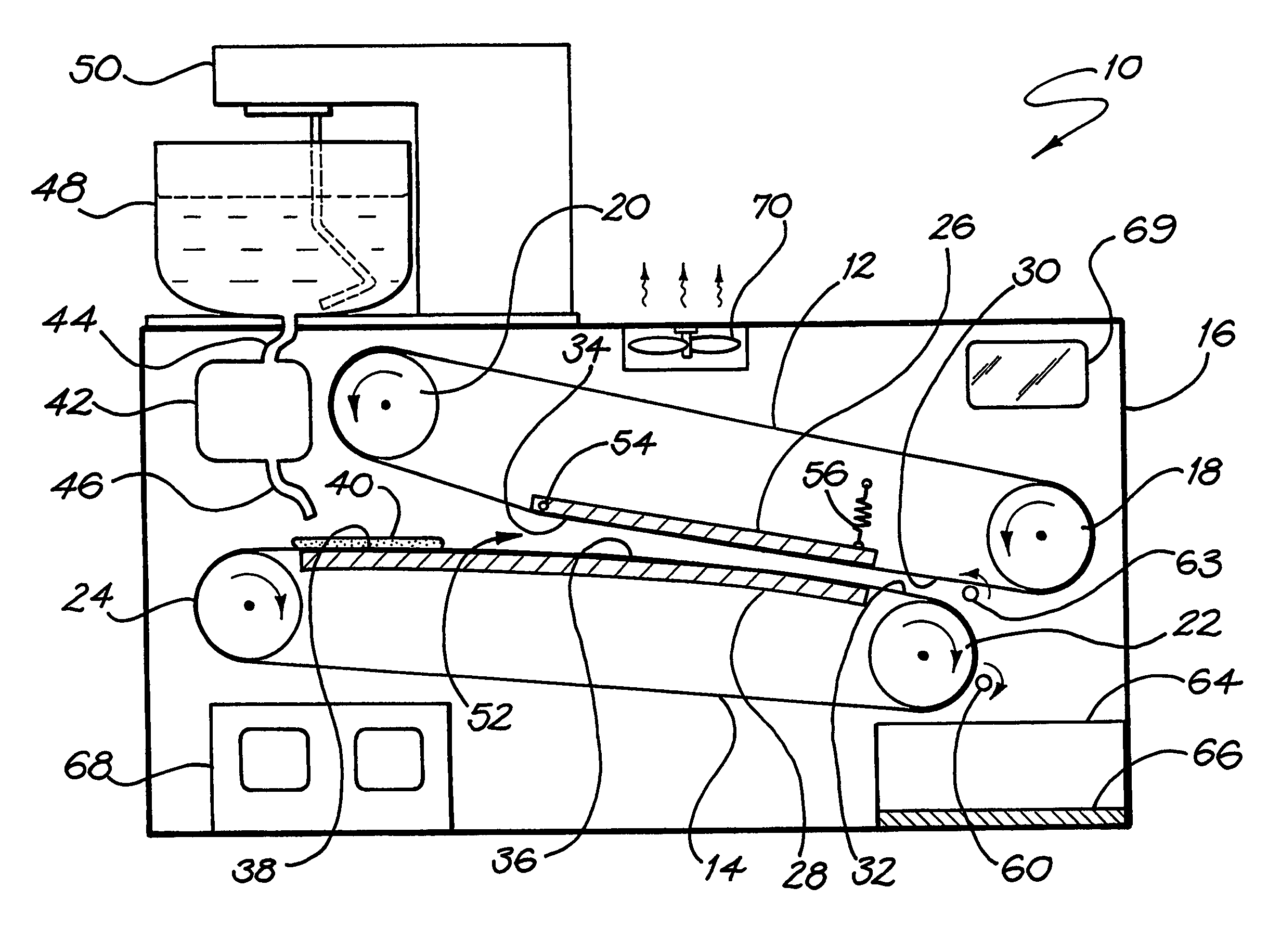
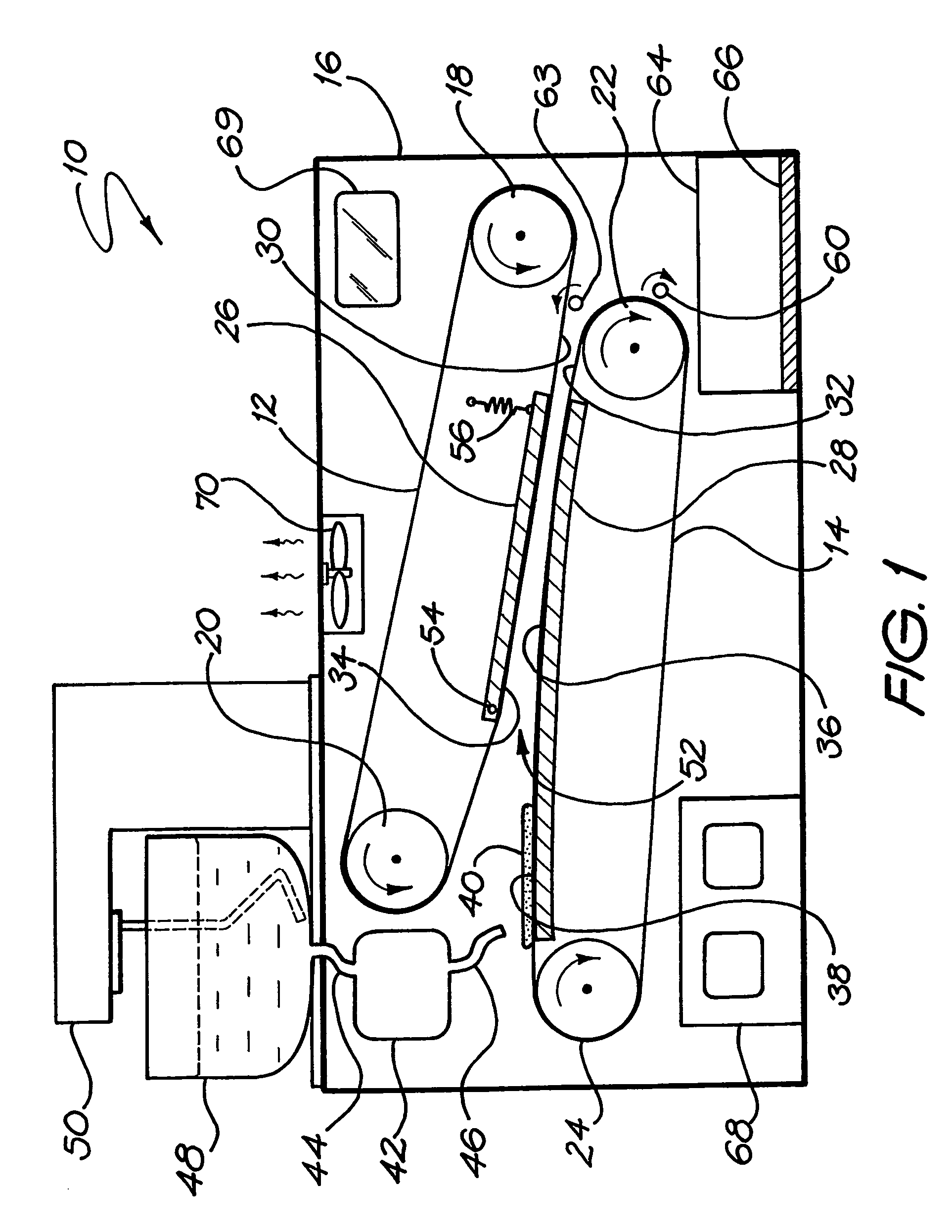
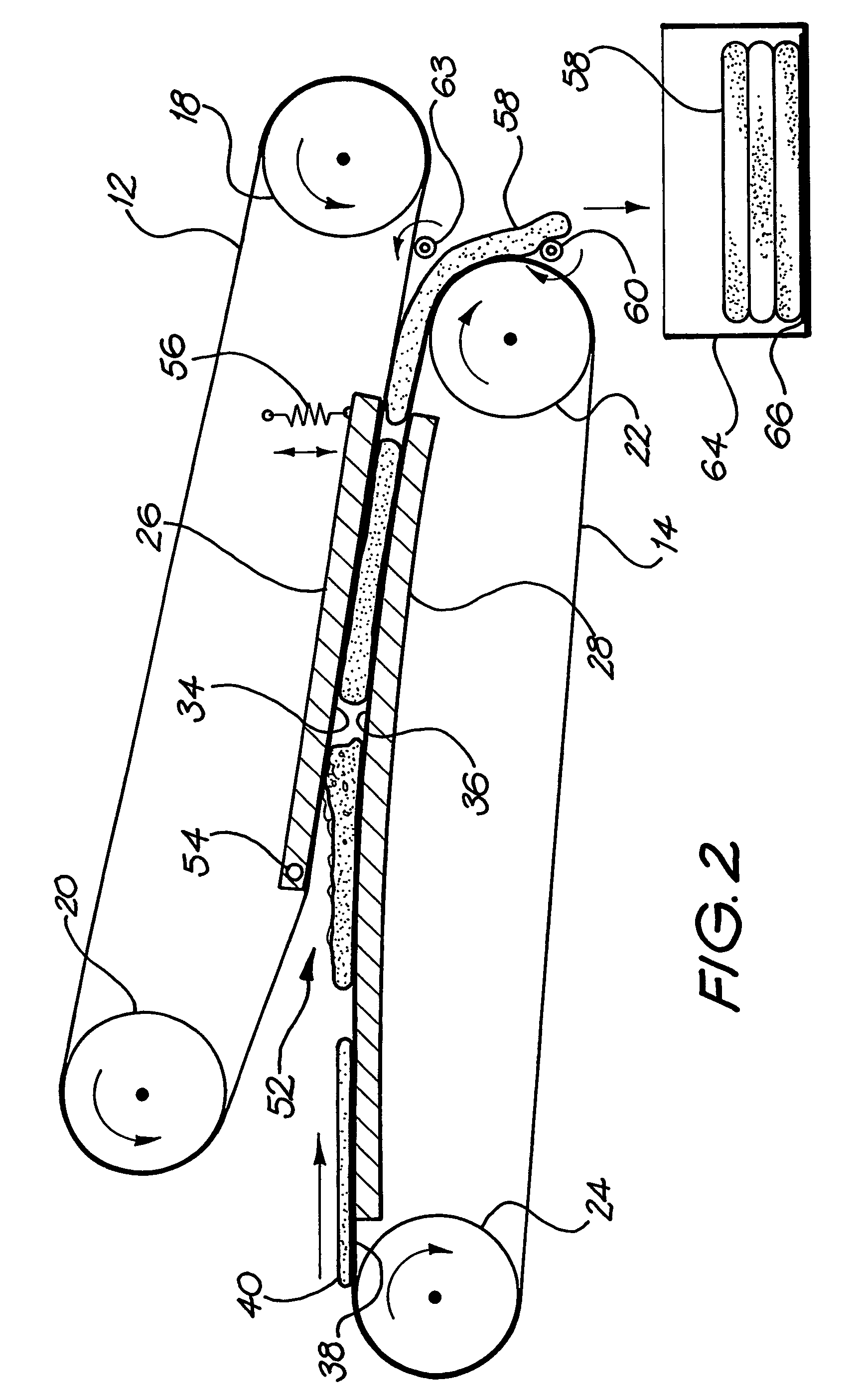
[0022]The automated belt cooking machine 10 shown in FIG. 1 includes an upper belt 12 and a lower belt 14 mounted to a frame 16. The upper belt 12 is rotated in an anticlockwise direction over motor driven roller 18 and idler roller 20, and the lower belt 14 is rotated in a clockwise direction over motor driven roller 22 and idler roller 24. The upper and lower belts 12, 14 are, in this embodiment, fabricated of a thin fibreglass fabric coated with Teflon, to provide sufficient flexibility, high temperature resistance, thermal conductance, and non-stick characteristics to releasably support and cook most foods.

[0023]The upper belt 12 surrounds an upper heating platen 26, and the lower belt 14 surrounds a lower heating platen 28, the platens 26, 28 being heated electrically in this embodiment. The platens 26, 28 are in thermal contact with sections of the bottom and top runs 30, 32 respectively, of the belts 12, 14 so that heat generated by the platens 26, 28 is transferred to those ...


PUM


Abstract

An automated belt cooking machine (10) for pancakes and the like food products has upper and lower overlapping, thermally conductive belts (12, 14), counter-rotatably mounted to a frame (16) so that, in use, a bottom run (30) of the upper belt (12) and a top run (32) of the lower belt (14) co-operate to convey food (40) to be cooked. The lower belt (14) extends a predetermined distance to one side of the upper belt (12) so as to provide a dispensing platform portion (38) for dispensing thereon the food to be cooked (40), so that the food (40) is conveyed towards a mouth (52) formed between the upper belt and lower belts (12, 14) and thereafter is conveyed sandwiched between the bottom and top run (30, 32). Upper and lower heating platens (26,28) are mounted to the frame (16) and are in thermal contact with the bottom and top run (30, 32), wherein the food to be cooked (40) is initially exposed to heat from the lower platen (28) conducted through the dispensing platform portion (38).

Description

FIELD OF THE INVENTION[0001]The present invention relates to an automated belt cooking machine for pancakes or the like food products. In particular, the present invention relates to an improved machine for cooking pancakes by dispensing a liquid batter onto a movable thermally conductive belt and bringing the liquid batter into thermal contact with upper and lower electrically heated platens or hot plates. More particularly, the present invention relates to such an improved machine having a pair of overlapping, counter-rotating, thermally conductive belts in which the liquid batter is deposited onto a lower or underlying belt in thermal contact with a lower platen and then conveyed in the direction of an upper or overlying belt in thermal contact with an upper platen so that the batter enters the mouth between the counter-rotating belts with its bottom surface first exposed to heating before its top surface, thereby assisting in the release of gases trapped in bubbles produced by h...

Claims


Application Information

Patent Timeline
Patent Type & Authority Patents(United States)
IPC IPC(8): A47J37/00A21B1/48A21B5/03A47J37/04
CPCA21B5/03
Inventor SZYMANSKI, MAREK
Owner SZYMANSKI MAREK
Learn More