Apparatus for handling and racking pipes

a technology for racking pipes and apparatus, which is applied in the direction of fluid removal, lifting devices, applications, etc., can solve the problems of affecting the racking rate, the mid-portion and lower portion of the pipe is vulnerable to undesired swaying movement, and the inability to provide a solution to address the instability associated with manipulating and transporting pipe stands, etc., to achieve the effect of increasing the racking rate and increasing the racking efficiency

Active Publication Date: 2008-02-19
WEATHERFORD CANADA
View PDF14 Cites 48 Cited by
  • Summary
  • Abstract
  • Description
  • Claims
  • Application Information

AI Technical Summary

Benefits of technology

[0007]In accordance with the present invention, there is provided an apparatus for handling pipes in a drilling derrick wherein the apparatus stabilizes and supports the pipe stand such that unwanted movement of the pipe stand, which affects the rate of racking, may be reduced, thereby increasing racking efficiency.
[0008]In accordance with the present invention, there is provided an apparatus for handling pipes in a drilling derrick and racking the pipes on a pipe racking assembly mounted to the derrick, the apparatus comprising a rotatable gate assembly mounted to the pipe racking assembly. The rotatable gate assembly includes a substantially U-shaped collar and an arm. The collar defines a gate opening to receive and secure an upper portion of a pipe stand and the collar is rotatably mounted to a first end of a shaft. The first end of the arm is pivotably and rotatably mounted to a second end of the shaft and a releaseable pipe mount is mounted to the second end of the arm to engage a predetermined portion of the pipe stand. The releseable pipe mount comprises a first securing means which engages a mid-portion of the pipe stand and a second securing means mounted to the first securing means such that the second securing means may securely engage a lower portion of the pipe stand. The first securing means and the second securing means provides support and stability to the pipe stand when the pipe stand engages the first and the second securing means.
[0010]In another embodiment of the invention, the arm is operable by a second actuator such that the arm may displace between a vertical position substantially parallel to the pipe stand and an angled position. The arm may displace between the vertical position and the angled position such that the arm may securely engage the first and the second securing means to the pipe stand. The arm may also displace between the vertical position and the angled position such that the arm may transfer the pipe stand securely engaged to the first and said second securing means to the pipe racking assembly. When the arm retracts to the vertical position after the first and said second securing means securely engages the pipe stand, the collar receives the upper portion of the pipe stand in the gate opening such that the gate opening may prevent movement of the upper portion of the pipe stand.

Problems solved by technology

While the prior art provides devices for handling pipe stands in a more efficient manner, they do not provide a solution to address the instability associated with manipulating and transporting pipe stands that may exceed thirty feet in length and several hundred tonnes in weight.
For example, in the Krueger patent, a clamp engages only an upper portion of the pipe to effect vertical and rotational movement, leaving the mid-portion and lower portion of the pipe vulnerable to undesired swaying movement which may affect the racking rate.
Furthermore, the repeated use of clamps and other similar securing means causes scarring of the pipe stands which eventually causes weakening and breakage of the pipe stands.
Conventional securing means used in the art also fails to provide proper or adequate support of the weight of the pipe stand.
Therefore, an unaddressed need exists in the industry to provide an apparatus for handling pipes in a stable and efficient manner to deal with deficiencies and inadequacies in the prior art.

Method used


Image

  • Apparatus for handling and racking pipes
  • Apparatus for handling and racking pipes
  • Apparatus for handling and racking pipes

Examples


Embodiment Construction

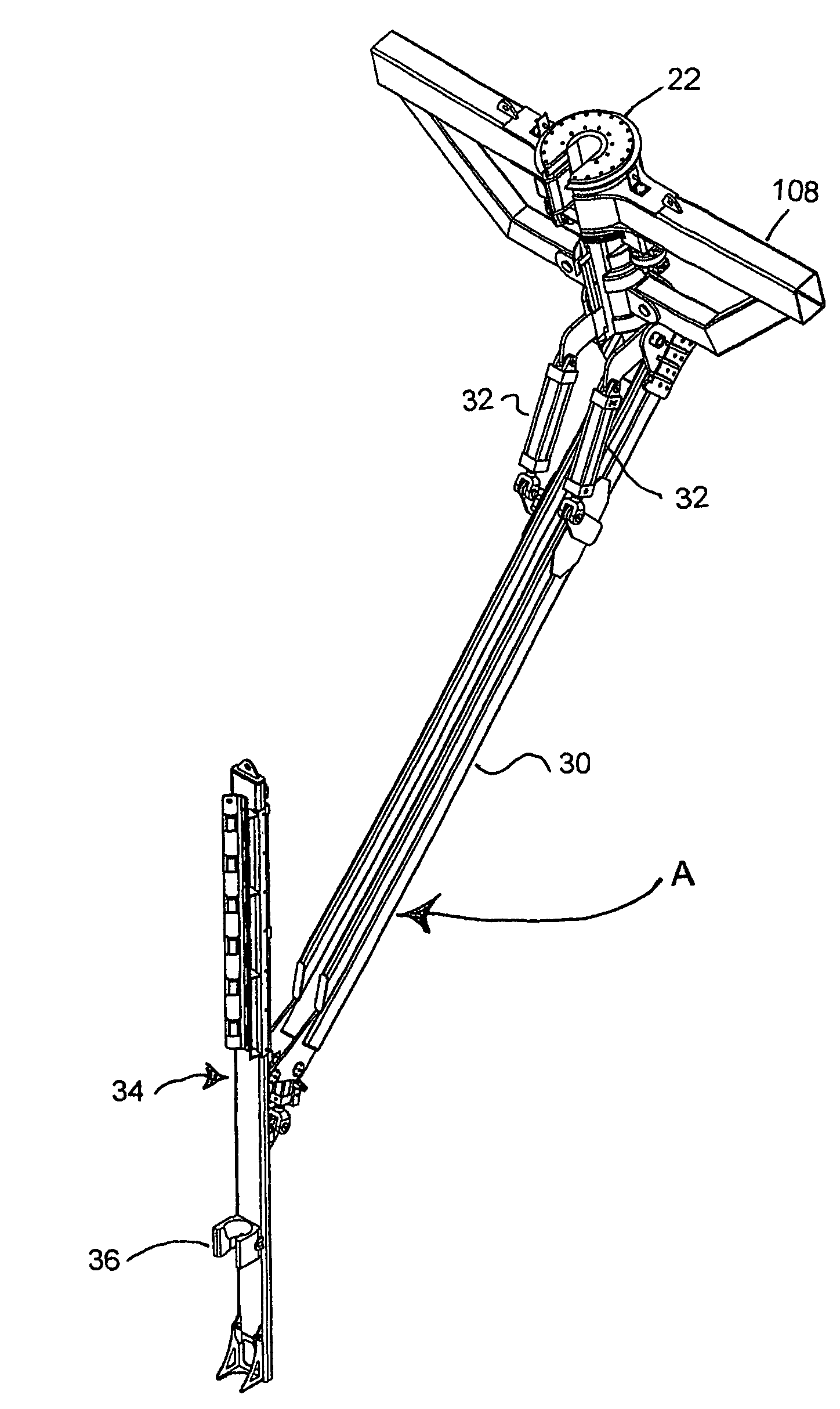
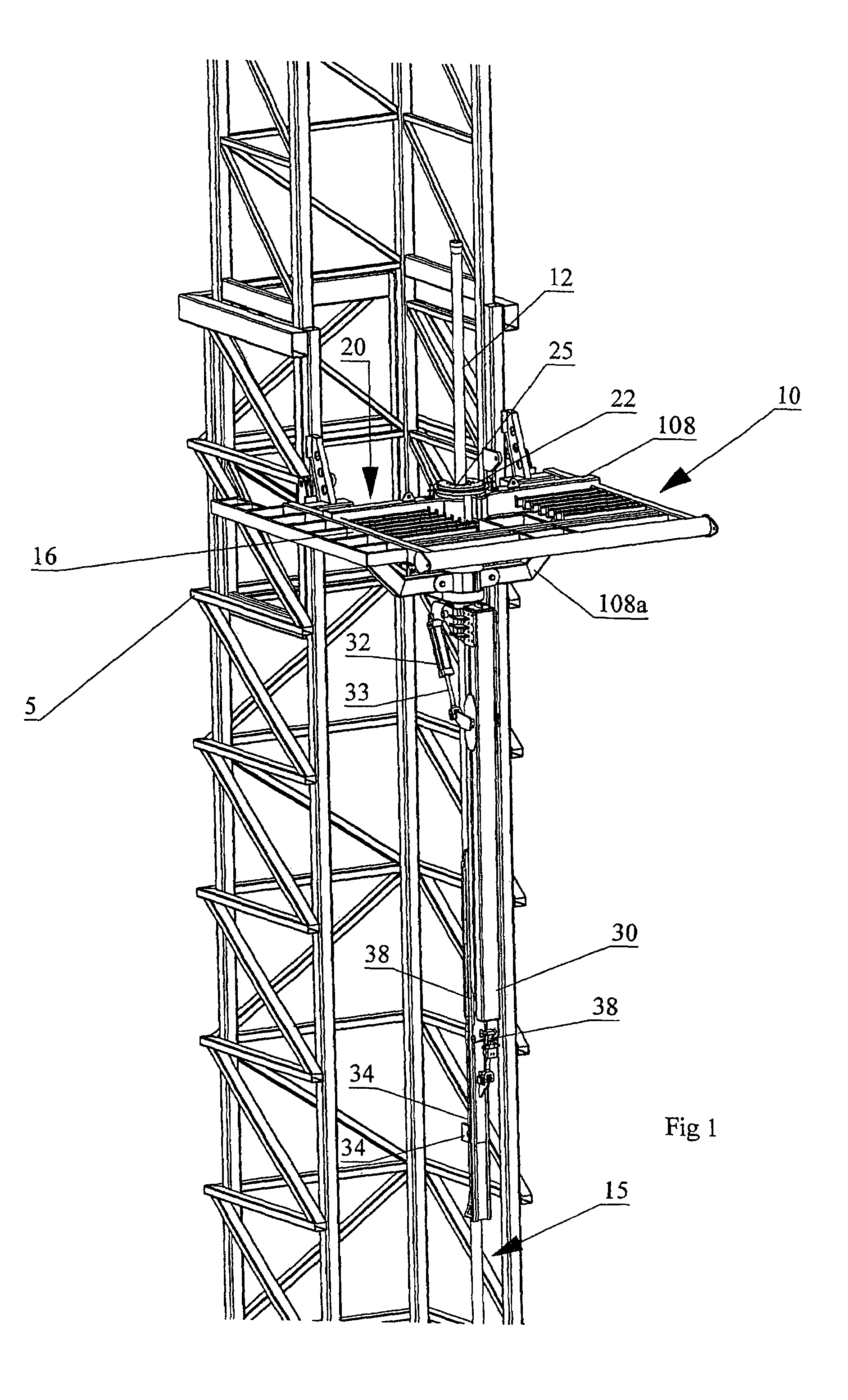
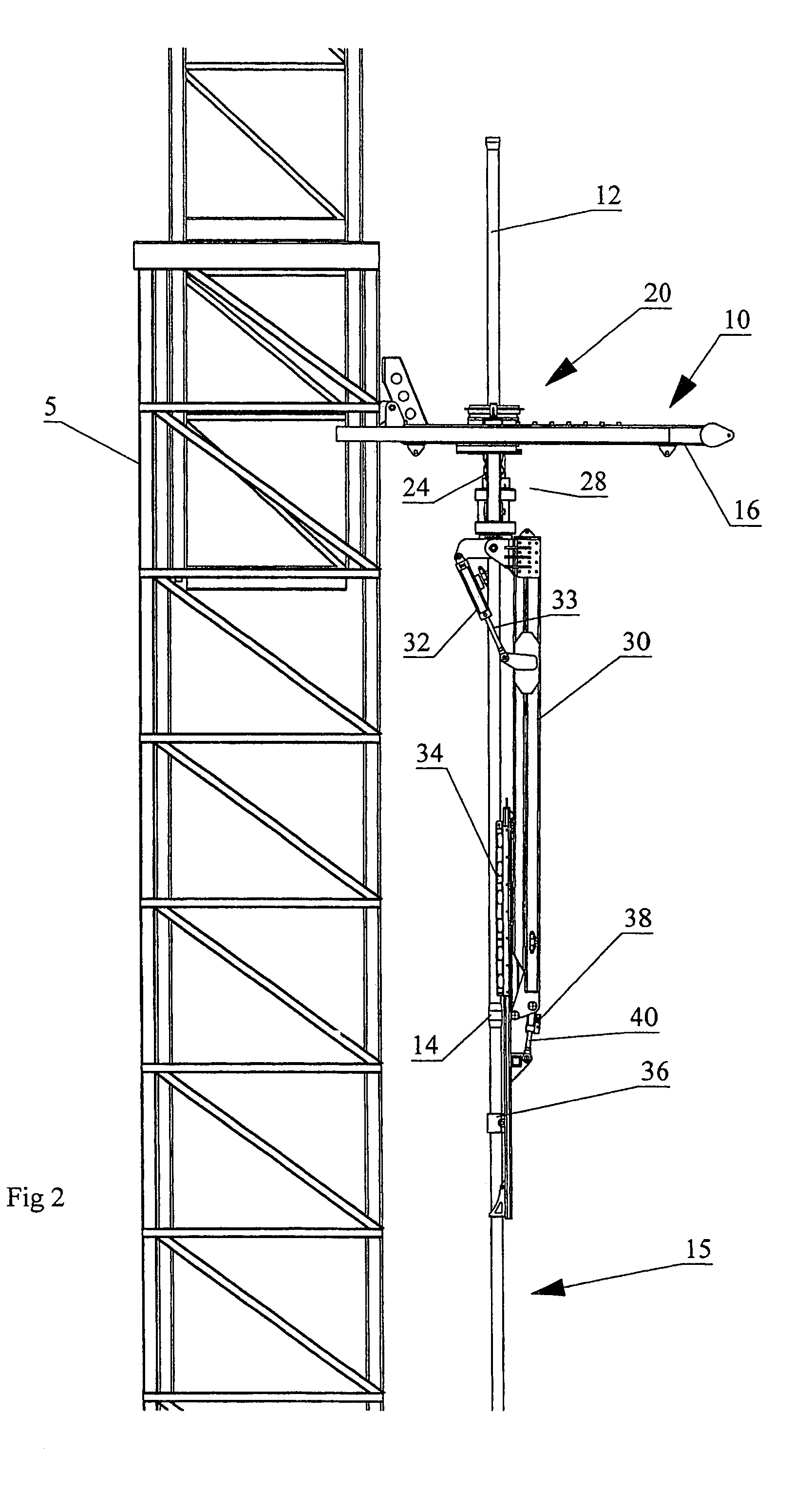
[0024]With reference to FIGS. 1 to 5 wherein similar characters of reference denote corresponding parts in each view, the apparatus for handling pipes according to the present invention includes a derrick 5, a pipe racking assembly 10 mounted to derrick 5, and a rotatable gate assembly 20 mounted to pipe racking assembly 10. In an embodiment of the present invention, the apparatus for handling pipes is configured to handle and rack a plurality of pipe stands 12 which are detachably coupled together to form a drill string 15. Pipe stands 12 are formed by coupling a plurality of pipe joints together. The ends of each pipe joint are flared such that at the point of coupling between pipe joints and pipe stands 12, an annular flange known in the art as a tool joint 14 is formed.

[0025]In an embodiment of the invention, pipe racking assembly 10 is generally rectangular in shape and horizontally disposed. Pipe racking assembly 10 is mounted to a mid-portion of derrick 5 such that pipe racki...


PUM


Abstract

An apparatus for handling pipes in a derrick and racking the pipes on a pipe racking assembly mounted on the derrick is provided to improve the stability of transferring pipes during a round trip operation. The apparatus includes a rotatable gate assembly mounted on the pipe racking assembly. The rotatable gate assembly includes a collar rotatably mounted to a first end of a shaft and an arm pivotably and rotatably mounted on a second end of the shaft. The collar defines a gate for securing an upper portion of the pipe stand. A first securing means mounted to a second end of the arm secures the mid-portion of the pipe stand and a second securing means mounted to the first securing means secures the lower portion of the pipe stand. After the arm secures the pipe stand from the derrick, a drive mechanism mounted to the shaft rotates the rotatable gate assembly such that the arm may rack the pipe on the pipe racking assembly.

Description

FIELD OF THE INVENTION[0001]This invention relates to the field of equipment used in the drilling industry, and more particularly, it relates to an apparatus for manipulating and racking pipes in a drilling derrick.BACKGROUND OF THE INVENTION[0002]In drilling operations, the derrick is the structure designed to support and manipulate the drill string in and out of the well bore. The drill string is a series of drill pipe segments detachably connected together. Typically, the drill pipe segments are coupled together to form a pipe stand of a predetermined or standard length and the pipe stands are then coupled together to form the drill string.[0003]A drill collar and a drill bit are attached to a drill end of the drill string. The drill collar is a heavier pipe having a larger diameter which fits around the drill pipe and places weight on the drill bit such that the downward force from the weight of the drill string, drill collar, and other drilling equipment on the drill bit assist...

Claims


Application Information

Patent Timeline
Patent Type & Authority Patents(United States)
IPC IPC(8): E21B19/00A01G23/02
CPCE21B19/20
Inventor WRIGHT, MONTE NEILSTROSHEIN, WILLIAM JOHNRICHARD, DAVID LOUISBANISTER, ANDREW SCOTT
Owner WEATHERFORD CANADA
Why Eureka
Try Eureka