Cable connectors with internal fluid reservoirs

a technology of fluid reservoir and connector, which is applied in the direction of connection of connection contact member material, cable fitting in presence of gas/oil, coupling device connection, etc., and can solve the problems of time-consuming and difficult coordination

Inactive Publication Date: 2008-02-19
UTILX CORP
View PDF30 Cites 19 Cited by
  • Summary
  • Abstract
  • Description
  • Claims
  • Application Information

AI Technical Summary

Problems solved by technology

Removing the fluid feed tank from the cable system and preparing the injection termination for permanent use is time consuming and difficult to coordinate from an operations standpoint.

Method used


Image

  • Cable connectors with internal fluid reservoirs
  • Cable connectors with internal fluid reservoirs
  • Cable connectors with internal fluid reservoirs

Examples


Embodiment Construction

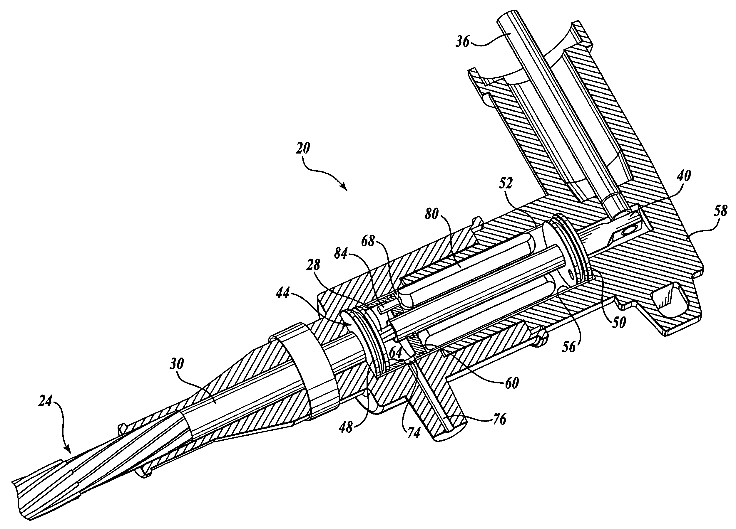
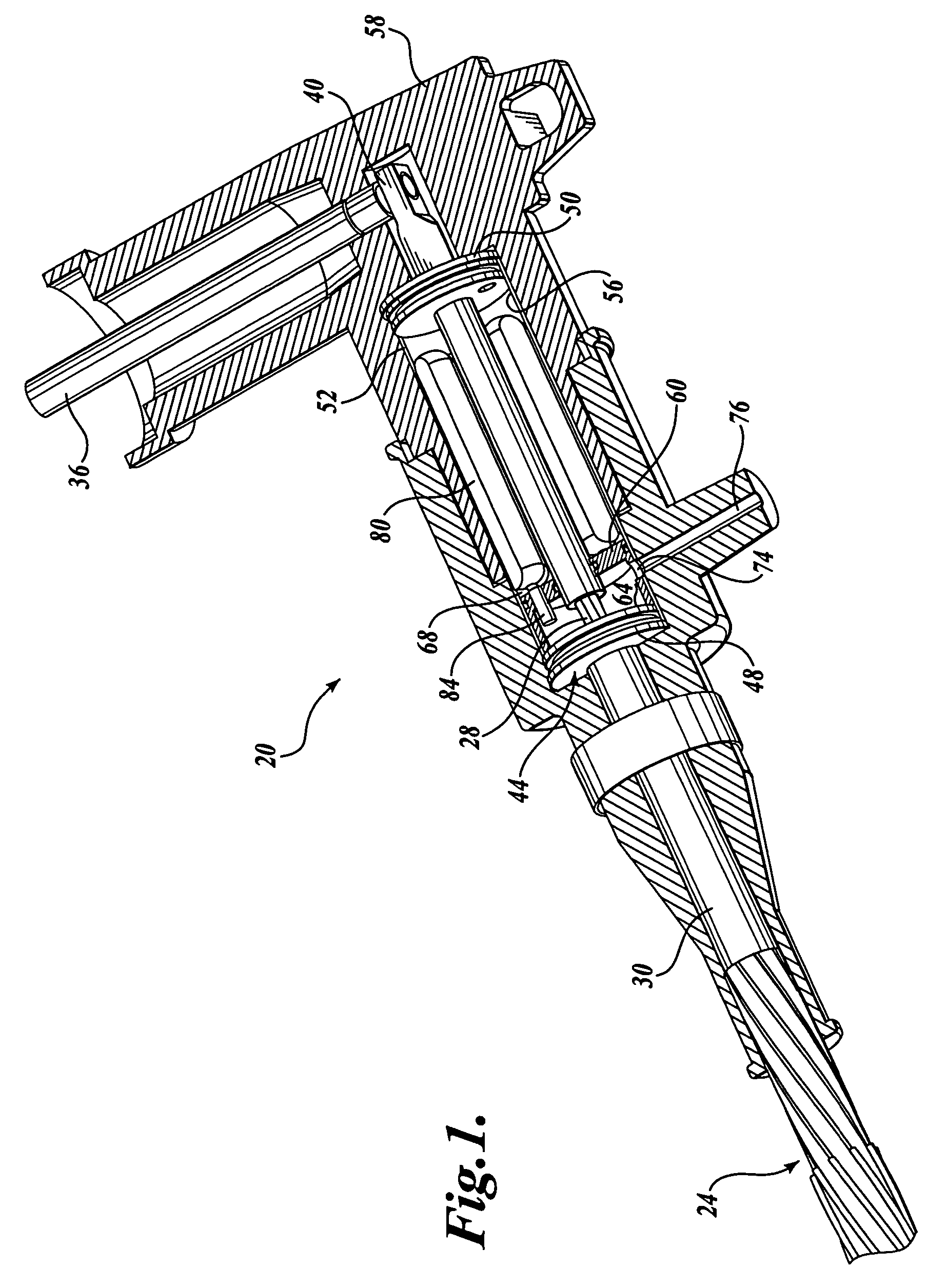
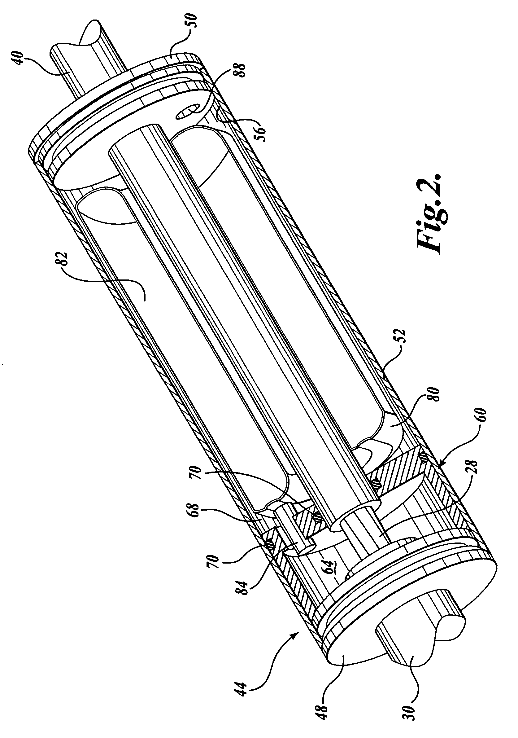
[0029]The present invention will now be described with reference to the drawings where like numerals correspond to like elements. Embodiments of the present invention are generally directed to cable terminations, junctions, or connectors that include an internal cavity that is capable of (1) holding a selected volume of remediation fluid and (2) supplying it to the cable. Several embodiments of the cavity are capable of holding the remediation fluid under pressure for prolonged periods of time and through various environmental conditions, such as temperature, moisture and sun exposure.

[0030]As will be described in detail below, several embodiments of the internal cavity are divided into two or more chambers that are in physical communication through the opposition of pressure but which are chemically isolated. One chamber is in contact with the cable and is used to store and supply the remediation fluid. In several embodiments, the second chamber contains an actuation device, such a...


PUM


Abstract

Cable terminations, junctions, or connectors having a cable affixed therein are provided, which include an internal cavity that is capable of (1) holding a selected volume of remediation fluid and (2) supplying it to the cable. Several embodiments of the cavity are capable of holding the remediation fluid under pressure for prolonged periods of time and through various environmental conditions such as temperature, moisture and sun exposure. Several embodiments of the internal cavity are divided into two or more chambers that are in physical communication through the opposition of pressure but which are chemically isolated. In several embodiments, an actuation device, such as a spring or compressed gas, pressurizes the fluid. Throughout the embodiments, individual access port(s) provide controlled access to the various internal chambers.

Description

CROSS-REFERENCE TO RELATED APPLICATION[0001]This application claims the benefit of U.S. Provisional Application No. 60 / 604,506, filed Aug. 25, 2004, the disclosure of which is hereby expressly incorporated by reference.FIELD OF THE INVENTION[0002]The present invention relates to a remediation process for the insulation of power cables, and more particularly, to cable terminations and connectors that contain and supply remediation fluid to the power cables.BACKGROUND OF THE INVENTION[0003]One remediation process for the insulation of medium and high voltage power cables requires the injection of a remediation fluid into the free spaces of a cable's conductor. In many instances, the injection process takes place while the cables are energized. When the remediation process is performed on energized cables, a class of special injection terminations may be used. Injection terminations are similar to industry standard cable terminations except that they are sealed to the environment and h...

Claims


Application Information

Patent Timeline
Patent Type & Authority Patents(United States)
IPC IPC(8): H01R4/60
CPCH01R13/53H02G15/22H02G15/24
Inventor STAGI, WILLIAM R.STEELE, JAMES
Owner UTILX CORP
Why Eureka
Try Eureka