Breakpoint logic unit, debug logic and breakpoint method for a data processing apparatus

a data processing apparatus and logic technology, applied in software testing/debugging, instruments, electric digital data processing, etc., can solve the problem of not being able to generate a breakpoint signal

Active Publication Date: 2008-02-19
ARM LTD
View PDF14 Cites 75 Cited by
  • Summary
  • Abstract
  • Description
  • Claims
  • Application Information

AI Technical Summary

Benefits of technology

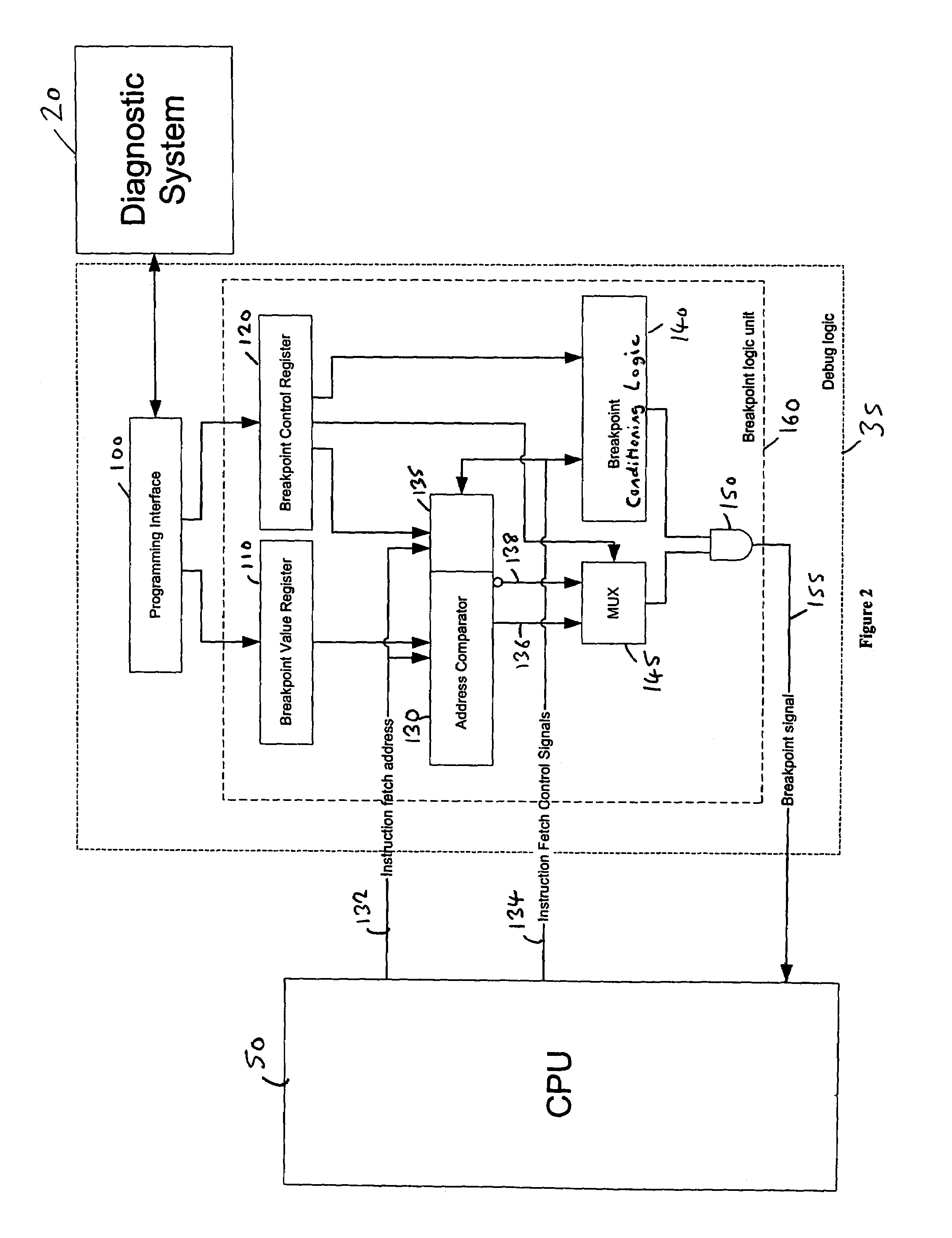
[0022]In an alternative embodiment, the data processing apparatus may use a plurality of different instruction sets, each of which has an associated width. For example, for the ARM instruction set this width is 4 bytes, for the Thumb instruction set this width is 2 bytes, and for the Java Virtual Machine instruction set this width is 1 byte. Within any particular instruction set, an instruction may consist of exactly one of the smallest addressable units, or alternatively the instruction set may comprise variable length instructions specified by one or more of the smallest addressable units for that instruction set. In embodiments where different instruction sets may be used by the processor, an instruction fetch may involve fetching a predetermined number of bytes starting from a particular instruction address. The number of instructions contained within those predetermined number of bytes may vary. In such embodiments, the at least one result signal comprises a plurality of result signals, and for each said result signal the breakpoint generation logic is operable to enable generation of an associated breakpoint signal if that result signal is set. In this embodiment, the use of the multiple result signals enables the generation of a corresponding multiple number of breakpoint signals, which can then be analysed by the processor based on an understanding of how many instructions are represented by the predetermined number of bytes fetched starting from the specified instruction address.
[0023]The match control signal can take a variety of forms. However, in one embodiment, the match control signal is a mismatch control signal, such that if the mismatch control signal is not set the comparator logic is operable to set the at least one result signal if a match is detected between said value and said selected value, whilst if the mismatch control signal is set the comparator logic is operable to set the at least one result signal if a match is not detected between said value and said selected value. Hence, by setting the mismatch control signal, the breakpoint logic unit will invert the sense of the comparison performed by the comparator logic.
[0025]However, in an alternative embodiment, said control storage is operable to store one or more further control values identifying one or more required conditions to be met in order for the at least one breakpoint signal to be generated, and the breakpoint logic unit further comprises: breakpoint conditioning logic operable to receive control signals generated by the data processing apparatus and associated with the value of said operational characteristic and to determine based on the received control signals whether said one or more required conditions are met; the breakpoint generation logic being operable, for each said result signal, to generate the associated breakpoint signal if both that result signal is set and said one or more required conditions are met. Hence, by this approach, the results of the comparison can be combined with other conditions in order to control the generation of the breakpoint signal(s), thus providing a great deal of flexibility as to the sequence of events that can give rise to the issuance of a breakpoint signal.
[0039]Viewed from a fourth aspect, the present invention provides a method of facilitating debugging in a data processing apparatus, comprising the steps of: providing a plurality of breakpoint logic units, each said breakpoint logic unit being operable to perform the method in accordance with the third aspect of the present invention; and employing combination logic to generate at least one breakpoint signal dependent on the breakpoint signals generated by each breakpoint logic unit.

Problems solved by technology

As the address of this instruction matches that in the value storage, the result signal will not be set, and accordingly generation of a breakpoint signal is not possible.

Method used


Image

  • Breakpoint logic unit, debug logic and breakpoint method for a data processing apparatus
  • Breakpoint logic unit, debug logic and breakpoint method for a data processing apparatus
  • Breakpoint logic unit, debug logic and breakpoint method for a data processing apparatus

Examples


Embodiment Construction

[0052]FIG. 2 illustrates the structure of a breakpoint logic unit 160 provided within the debug logic 35 in accordance with one embodiment of the present invention. In accordance with this embodiment, the breakpoint logic unit 160 includes comparator logic (consisting of an address comparator 130 and a multiplexer 145) for comparing a selected address value stored within the breakpoint value register 110 with an instruction fetch address received over path 132 from the CPU 50. The selected address value is programmed into the breakpoint value register 110 by the programming interface 100 under the control of the diagnostic system 20. As will be discussed in more detail later, the address comparator 130 may incorporate byte mask logic 135 for use in situations where variable length instructions are employed within the processing system incorporating the CPU 50. The address comparator produces an output signal over path 136 indicative of a match between the instruction fetch address a...


PUM


Abstract

The present invention provides a breakpoint logic unit, debug logic and breakpoint method for a data processing apparatus. The breakpoint logic unit comprises a value storage operable to store data indicative of a selected value for an operational characteristic of the data processing apparatus, and comparator logic operable to compare the selected value with a value of the operational characteristic as generated by the data processing apparatus. The comparator logic then generates at least one result signal indicative of a match between that value and the selected value. A control storage is also provided for storing a match control value, such that if the match control value has a first value the comparator logic is operable to set the at least one result signal if a match is detected between the value and the selected value, whilst if the match control value has a second value the comparator logic is operable to set the at least one result signal if a match is not detected between the value and the selected value. Breakpoint generation logic is then operable to enable generation of an associated at least one breakpoint signal if the at least one result signal is set. This has been found to provide a particularly flexible and efficient technique for enabling a variety of breakpoint conditions to be programmed within the breakpoint logic unit.

Description

BACKGROUND OF THE INVENTION[0001]1. Field of the Invention[0002]The present invention relates to a breakpoint logic unit, debug logic and breakpoint method for a data processing apparatus.[0003]2. Description of the Prior Art[0004]It is known to provide debug logic within a data processing apparatus to enable programs running on the data processing apparatus to be debugged by an external diagnostic system. An example of such a data processing apparatus is the processing system 10 of FIG. 1. The processing system 10 has a central processing unit (CPU) 50 provided therein, which is coupled to a memory system 65 via one or more buses to enable instructions and data to be passed between the CPU 50 and memory 65 as required by the CPU when executing one or more programs (as illustrated schematically by paths 55 and 60).[0005]Debug logic 35 is provided within the processing system 10 for interfacing to an external diagnostic system 20. The debug logic 35 contains registers for use by the ...

Claims


Application Information

Patent Timeline
Patent Type & Authority Patents(United States)
IPC IPC(8): G06F11/00G06F11/36G06F11/28
CPCG06F11/3648
Inventor WILLIAMS, MICHAEL JOHNKIMELMAN, PAULRIJK, JON ANDREW
Owner ARM LTD
Why Eureka
Try Eureka