
System and method for controlling a lighting system with a plurality of light sources

a technology of lighting system and light source, applied in the direction of light source, lighting apparatus, instruments, etc., can solve problems such as troublesome process, and achieve the effect of easy control

Active Publication Date: 2011-07-14
KONINKLIJKE PHILIPS ELECTRONICS NV
View PDF5 Cites 46 Cited by
  • Summary
  • Abstract
  • Description
  • Claims
  • Application Information

AI Technical Summary

Benefits of technology

[0004]It is an object of the invention to provide a system and method, which allows an easy control of a lighting system with a plurality of light sources, particularly an easy commissioning of light sources of a lighting system.
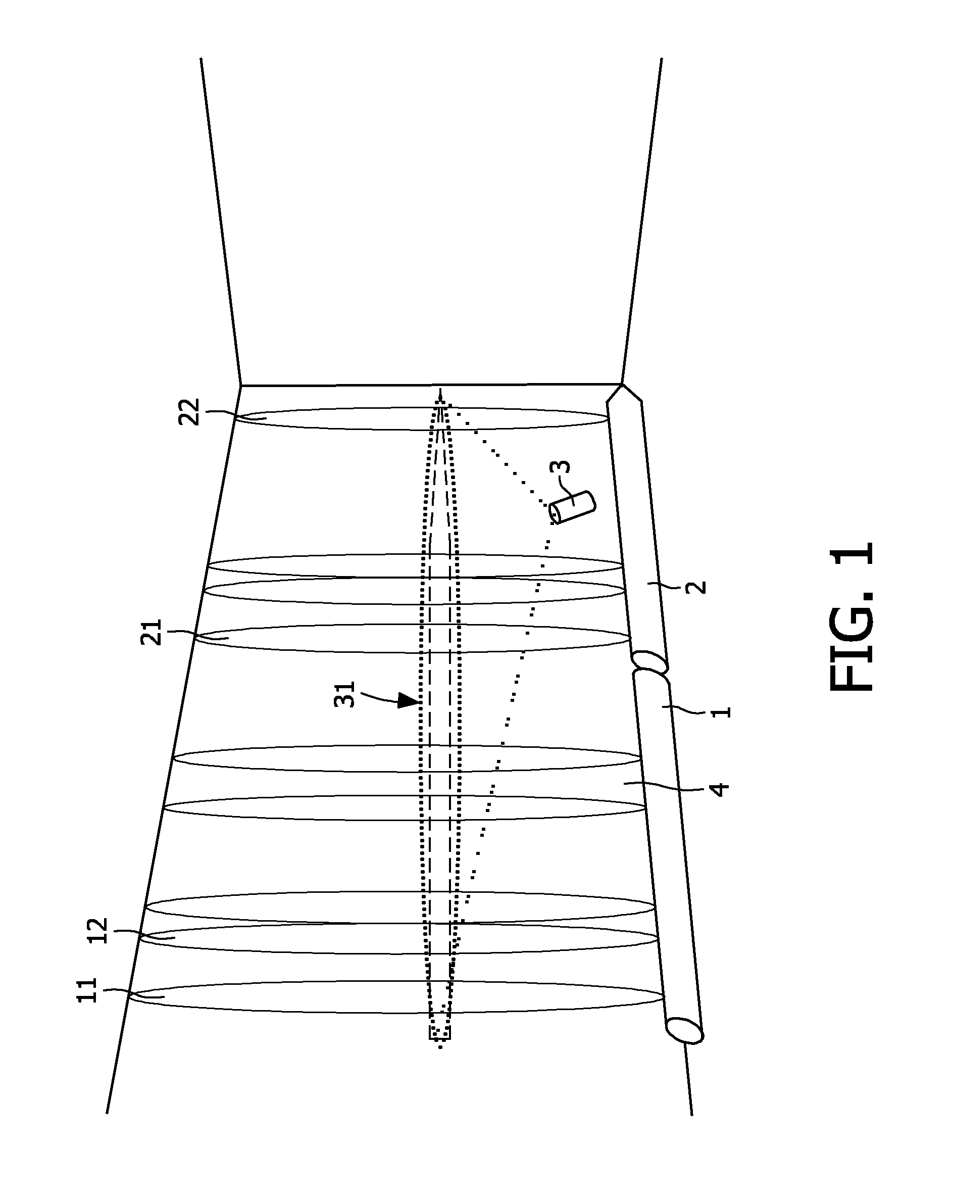
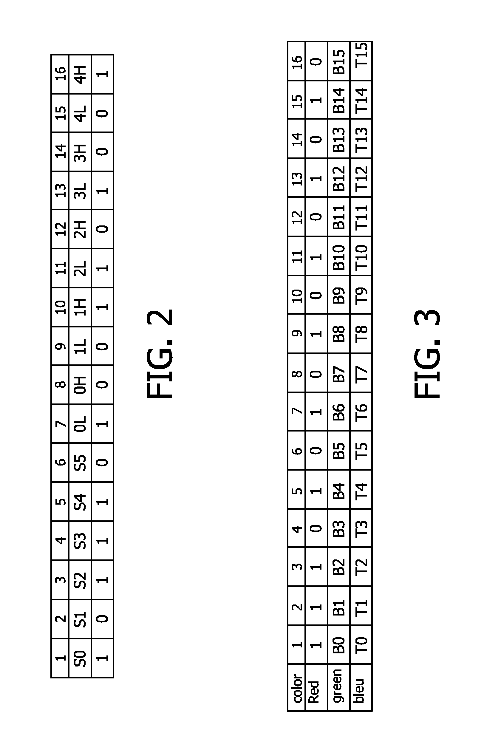
[0006]A basic idea of the invention is to use a spatial coding of light for controlling a lighting system, particularly for commissioning of light sources of the lighting system instead of or in addition to the temporal light coding as applied in the prior art, such as the lighting system known from WO2006 / 111930A1. A spatial coding is particularly suitable for wallwasher light sources, and thus especially assists personnel in commissioning wallwasher light sources of a lighting system. During commissioning of light sources, the lighting system sets the light sources to create a light pattern on a wall, which may be captured with a light pattern capturing device used by a user to commission light sources and decoded in order to obtain information on the light sources, such as position, sequence, spacing or address, of the light sources in the lighting system. Thus, an easy commissioning may be provided, which does not require the personnel to manually enter sequences of addresses of light sources in a light system controller of the lighting system.

Problems solved by technology

Many installed light sources in a number of locations, mean a tedious process of determining the addresses of the different light sources and program these into the light system controller.

Method used


Image

  • System and method for controlling a lighting system with a plurality of light sources
  • System and method for controlling a lighting system with a plurality of light sources
  • System and method for controlling a lighting system with a plurality of light sources

Examples


Embodiment Construction

[0051]In the following, functionally similar or identical elements may have the same reference numerals. Also, in the following description, the term “lamp”, “luminaire” and “light source” are used as synonyms, each meaning the same and describing any kind of controllable light source which can be used in lighting systems with a plurality of light sources.

[0052]In the following, the invention is explained by means of exemplary embodiments. The described embodiments are an alternative to coded light generated by a light source, i.e. to temporal coding or frequency coding of light, and are particularly suitable for easy commissioning of wallwasher light sources and other kind of light sources mounted in sequence, such as for example downlighters along a main way in a shop. In contrast to the temporal light coding, the invention uses spatial codes or spatial light patterns, which code information. Commissioning light sources can be done with a light pattern capturing device, which may ...


PUM


Abstract

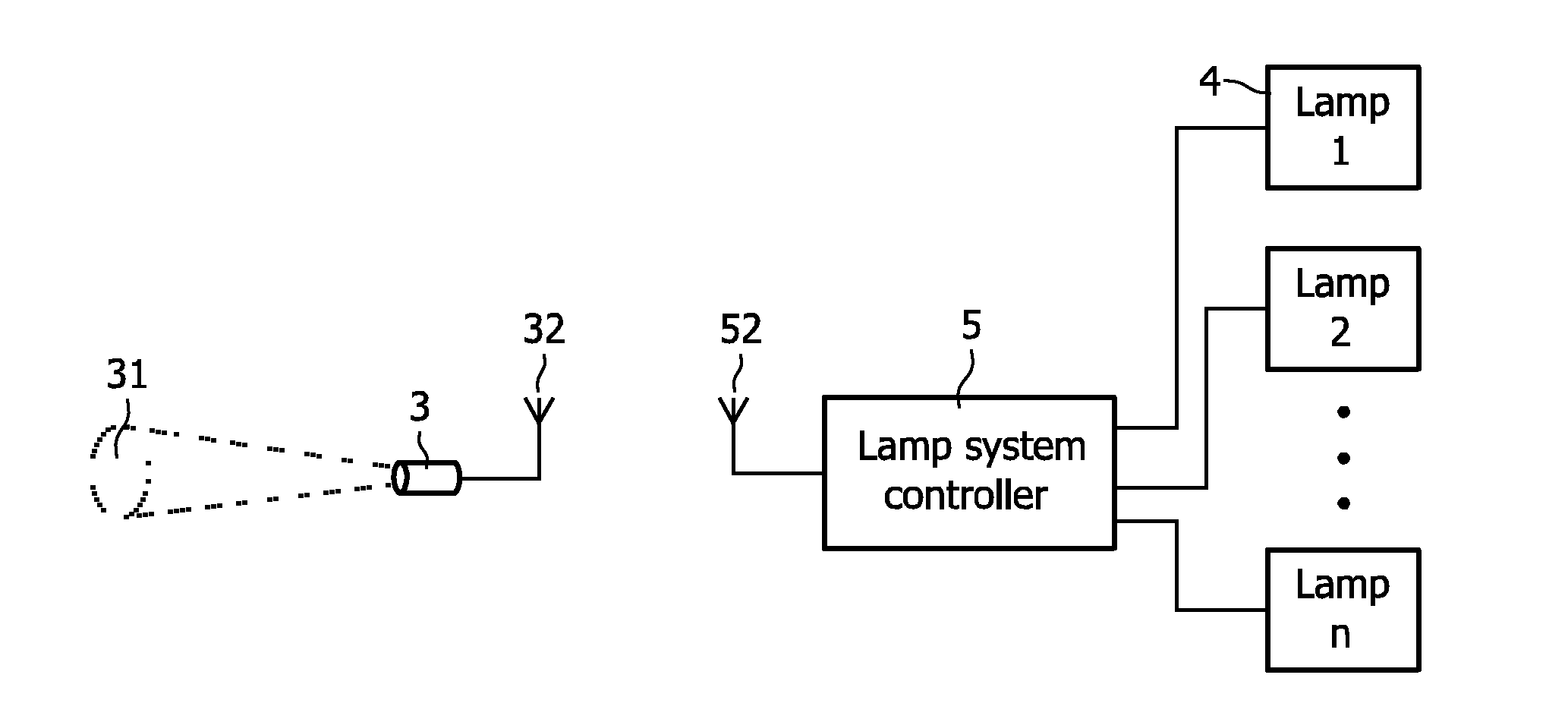
The invention relates to the controlling of a lighting system with a plurality of light sources, particularly to the semi-automatic commissioning of light sources of the lighting system or controlling of the creation of lighting scenes with the lighting system. A basic idea of the invention is to use a spatial coding of light for controlling a lighting system, particularly for commissioning of light sources of the lighting system instead of or in addition to the temporal light coding as applied in the prior art. An embodiment of the invention relates to a system for controlling a lighting system with a plurality of light sources (1, 2) comprising a light system controller (5) for controlling the light sources in that a spatial light pattern (11, 12, 21, 22) is created, which codes one or more attributes (512) of the light sources (511), and a light pattern capturing device (3) for capturing the created spatial light pattern and communicating (32, 52) with the light system controller (5) in order to enable the controlling of the one or more light sources based on the captured spatial light pattern. A spatial coding is particularly suitable for wallwasher light sources, and thus especially assists personnel in commissioning wallwasher light sources of a lighting system.

Description

FIELD OF THE INVENTION[0001]The invention relates to the controlling of a lighting system with a plurality of light sources, particularly to the semi-automatic commissioning of light sources of the lighting system or supporting the creation of lighting scenes with the lighting system.BACKGROUND OF THE INVENTION[0002]For decorative lighting often a high number of light sources such as luminaries have to be installed and the control systems for these light sources have to be configured correctly in order to reproduce the proper light effects in a location. Typical lamps for such application are often controlled via a certain control bus. Several lamps are connected to the same physical or logical bus. In order to control the lamps individually, the information on the control bus is arranged in a way that a lamp can determine which part of the total information on the bus is relevant for it. Each lamp has an address; based on this address, the lamps extract the relevant data. Many inst...

Claims


Application Information

Patent Timeline
Patent Type & Authority Applications(United States)
IPC IPC(8): H05B37/02
CPCH05B37/02H05B37/029H05B47/155H05B47/17H05B47/165H05B47/199H05B47/175H05B47/10
Inventor WENDT, MATTHIASRADERMACHER, HARALD J. G.LEYTEN, PAUL
Owner KONINKLIJKE PHILIPS ELECTRONICS NV
Learn More