Cooling system for a rotary screw compressor

a compressor and cooling system technology, applied in the direction of machines/engines, liquid fuel engines, light and heating apparatus, etc., can solve the problems of inhibiting the efficiency of the compressor system

Inactive Publication Date: 2008-02-26
SULLAIR CORP
View PDF14 Cites 17 Cited by
  • Summary
  • Abstract
  • Description
  • Claims
  • Application Information

AI Technical Summary

Problems solved by technology

If not reduced, the heat build-up may inhibit the efficiency of the compressor system.

Method used


Image

  • Cooling system for a rotary screw compressor
  • Cooling system for a rotary screw compressor
  • Cooling system for a rotary screw compressor

Examples


Embodiment Construction

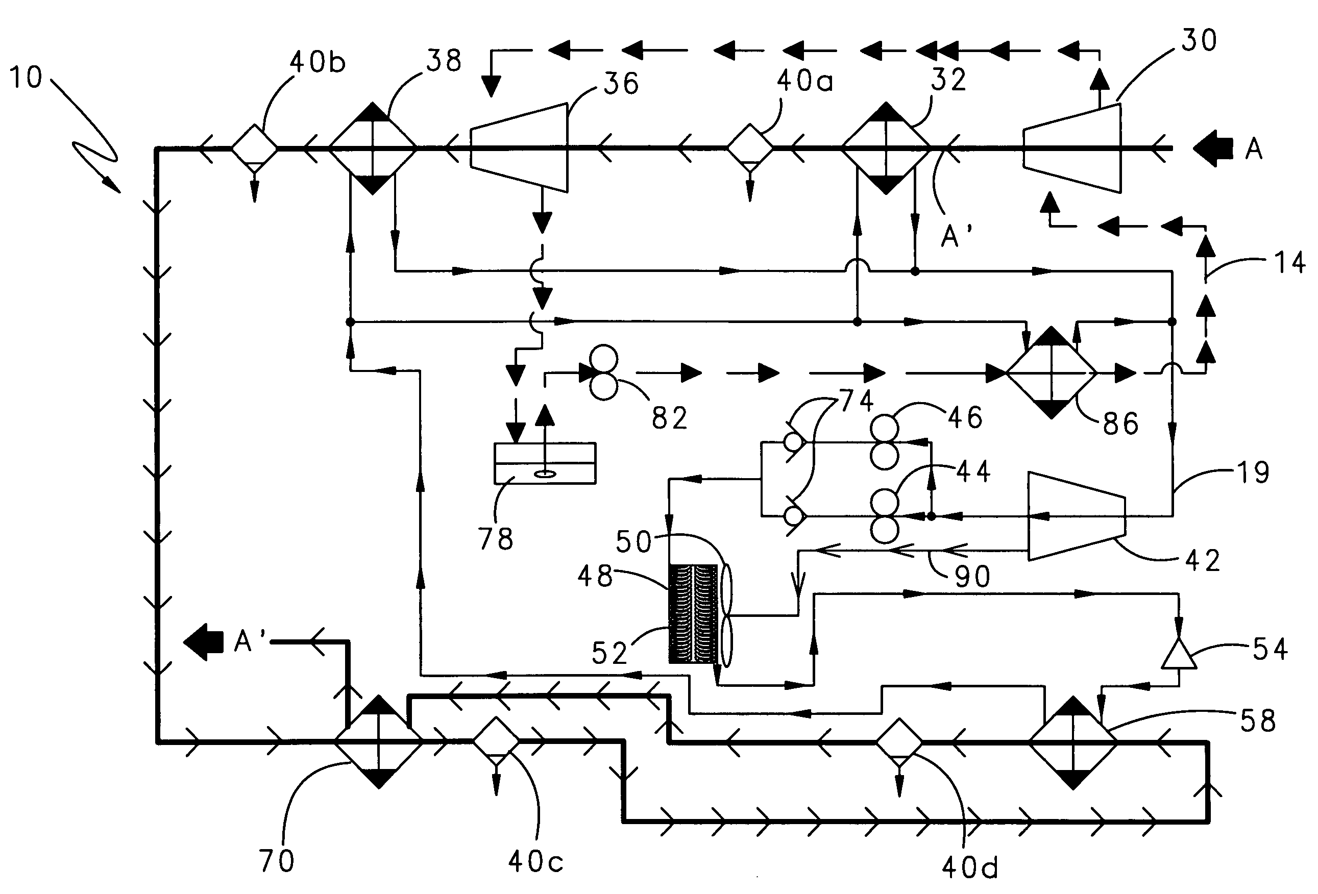
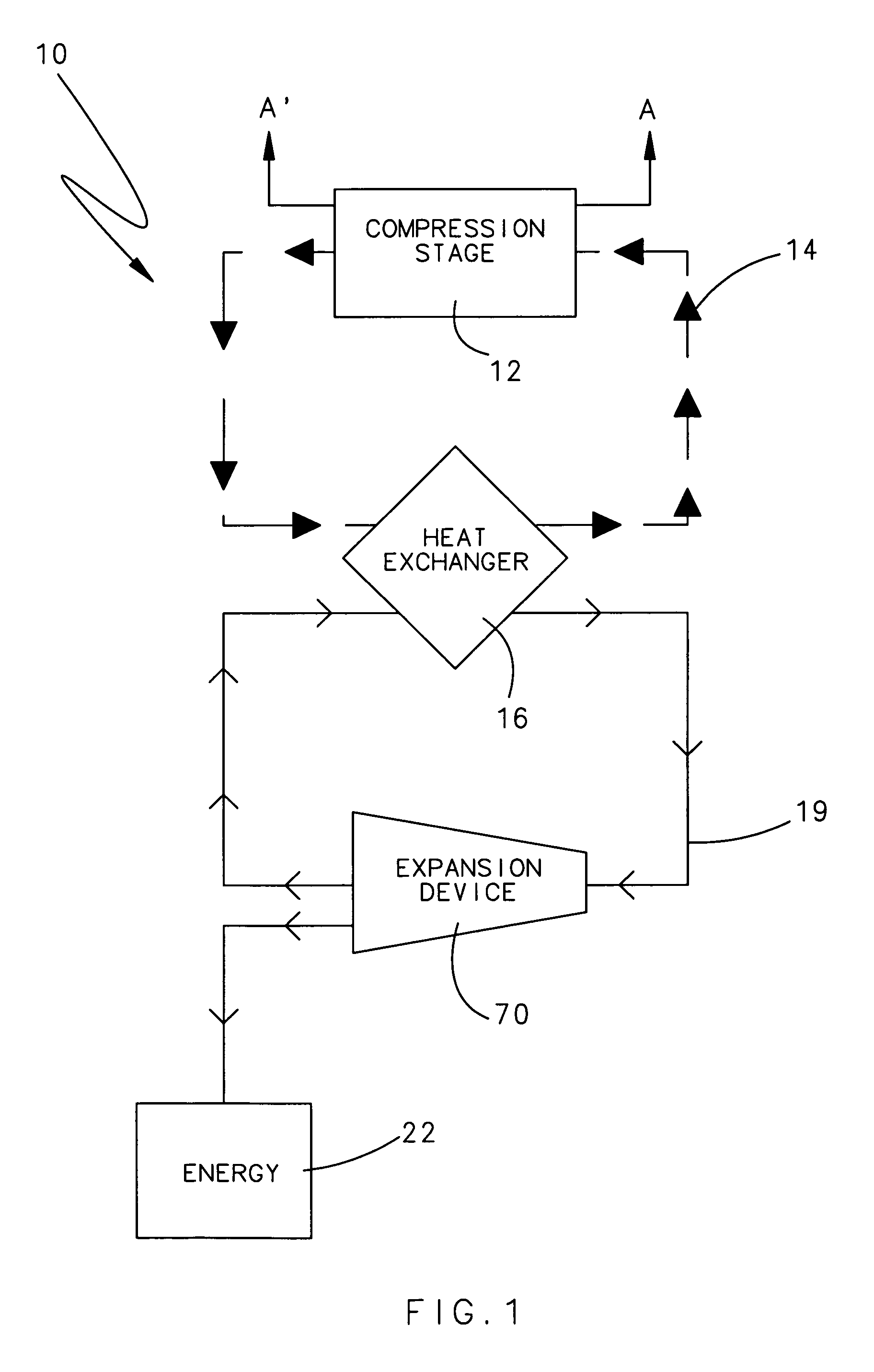
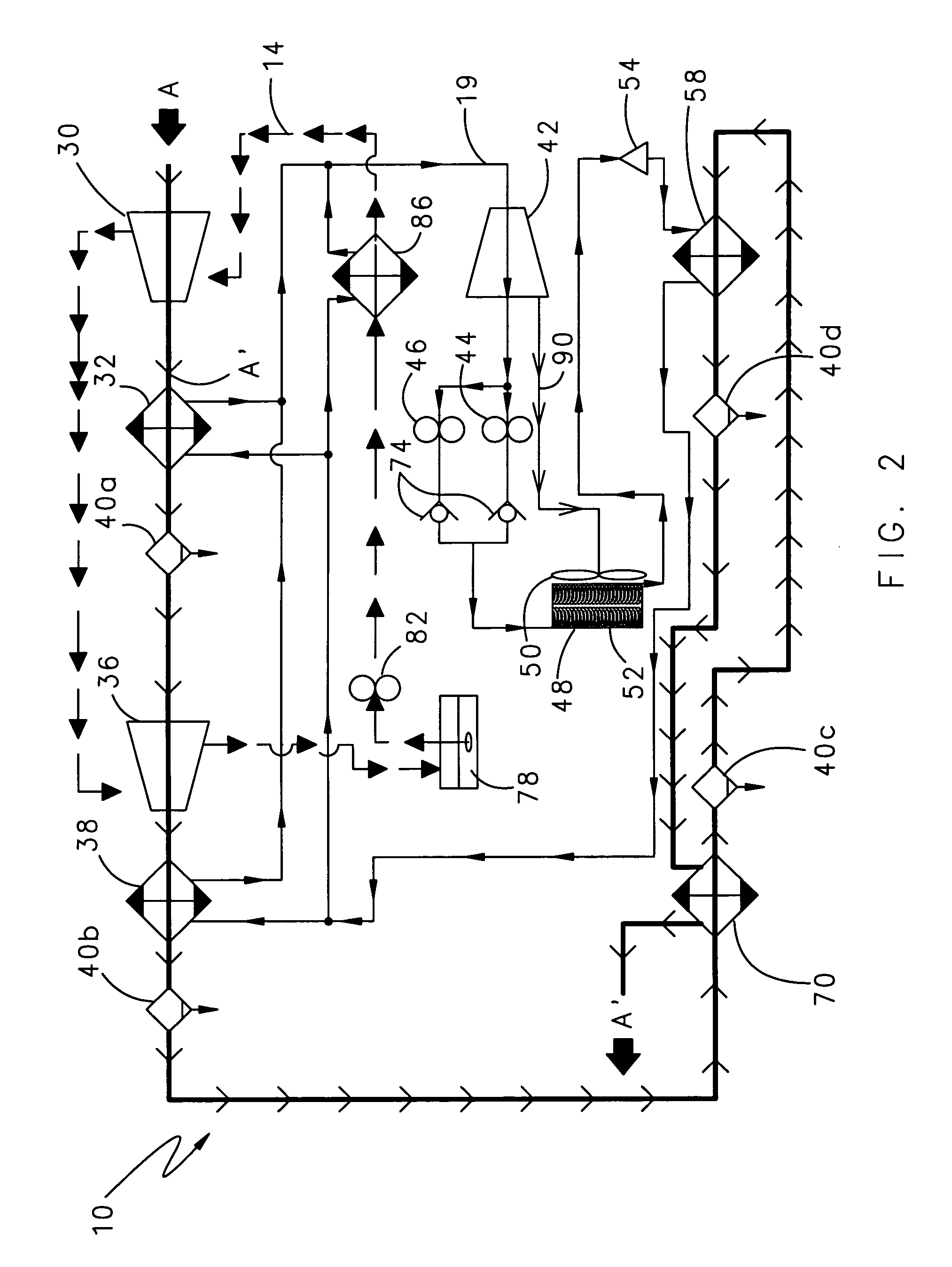
[0012]FIG. 1 illustrates a general schematic view of a screw compressor system 10 having a compression stage 12, a heat exchanger 16, and a refrigerant expansion device 20. The system 10 uses thermal energy generated during the compression stage 12 to drive at least one component of the screw compressor cooling system 10.

[0013]Ambient air A enters the compression stage 12 where one or more screw compressors compress the ambient air A to a desired compression level A′. A coolant, which may be oil, lubricates components of the compression stage 12 and fluidly communicates thermal energy from the compression stage 12 to the heat exchanger 16. The coolant communicates with the compression stage 12 and the heat exchanger 16 through a coolant circuit 14.

[0014]Within the heat exchanger 16, heat is communicated from the coolant to a refrigerant. In addition, compressed air A′ within the compression stage 12 may communicate heat to the refrigerant which increases the pressure of the refriger...


PUM


Abstract

A compressor system has a compression stage, a coolant circuit and a refrigerant circuit. The compression stage compresses ambient air and generates compressed air and heat. A coolant removes heat from the compression stage and the heat is transferred from the coolant to a refrigerant. A refrigerant expansion device is incorporated into the refrigerant circuit. The expansion device expands the pressurized refrigerant utilizing a rotary expander. Energy generated during refrigerant expansion is captured and used to drive components of the cooling system.

Description

BACKGROUND OF THE INVENTION[0001]This application relates to a cooling system for a compressor, which utilizes energy generated by a fluid expansion to power at least one component.[0002]Rotary screw compressors include one or more rotor systems having a male rotor and a female rotor, which rotate relative to each other to produce compressed air. During normal operation, the compressor system generates heat. If not reduced, the heat build-up may inhibit the efficiency of the compressor system.[0003]Thus, a liquid coolant is communicated through the compressor. The coolant absorbs thermal energy. The heated coolant is communicated to a heat exchanger, wherein heat is transferred to the ambient air or a liquid, which is dumped to waste. Electrically powered fans typically drive airflow through the liquid-to-air heat exchanger to remove the absorbed thermal energy.[0004]It would be desirable to utilize the thermal energy built-up in the coolant to reduce power requirements of the compr...

Claims


Application Information

Patent Timeline
Patent Type & Authority Patents(United States)
IPC IPC(8): F25B1/00
CPCF04C18/16F04C29/04F25B11/02F25B2400/141
Inventor HOLDSWORTH, JOHN
Owner SULLAIR CORP
Why Eureka
Try Eureka