Automatic detection and correction of non-red eye flash defects

a technology of automatic detection and correction, applied in image data processing, instruments, character and pattern recognition, etc., can solve the problems of poor information in the neighborhood about other facial features and therefore unreliabl

Inactive Publication Date: 2008-02-26
FOTONATION LTD
View PDF30 Cites 242 Cited by
  • Summary
  • Abstract
  • Description
  • Claims
  • Application Information

AI Technical Summary

Problems solved by technology

They resemble luminous dots and information in their neighborhood about other facial features is poor and therefore unreliable.

Method used


Image

  • Automatic detection and correction of non-red eye flash defects
  • Automatic detection and correction of non-red eye flash defects
  • Automatic detection and correction of non-red eye flash defects

Examples


Embodiment Construction

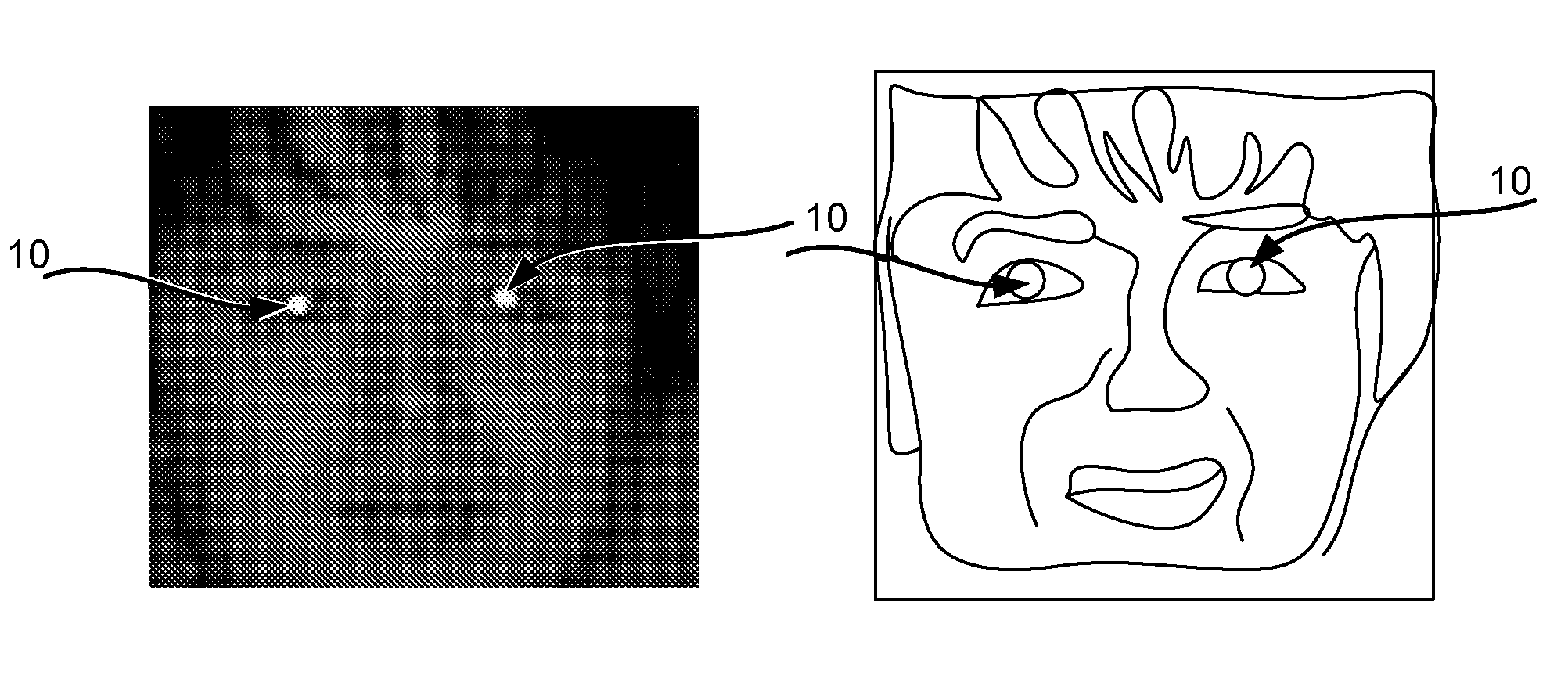
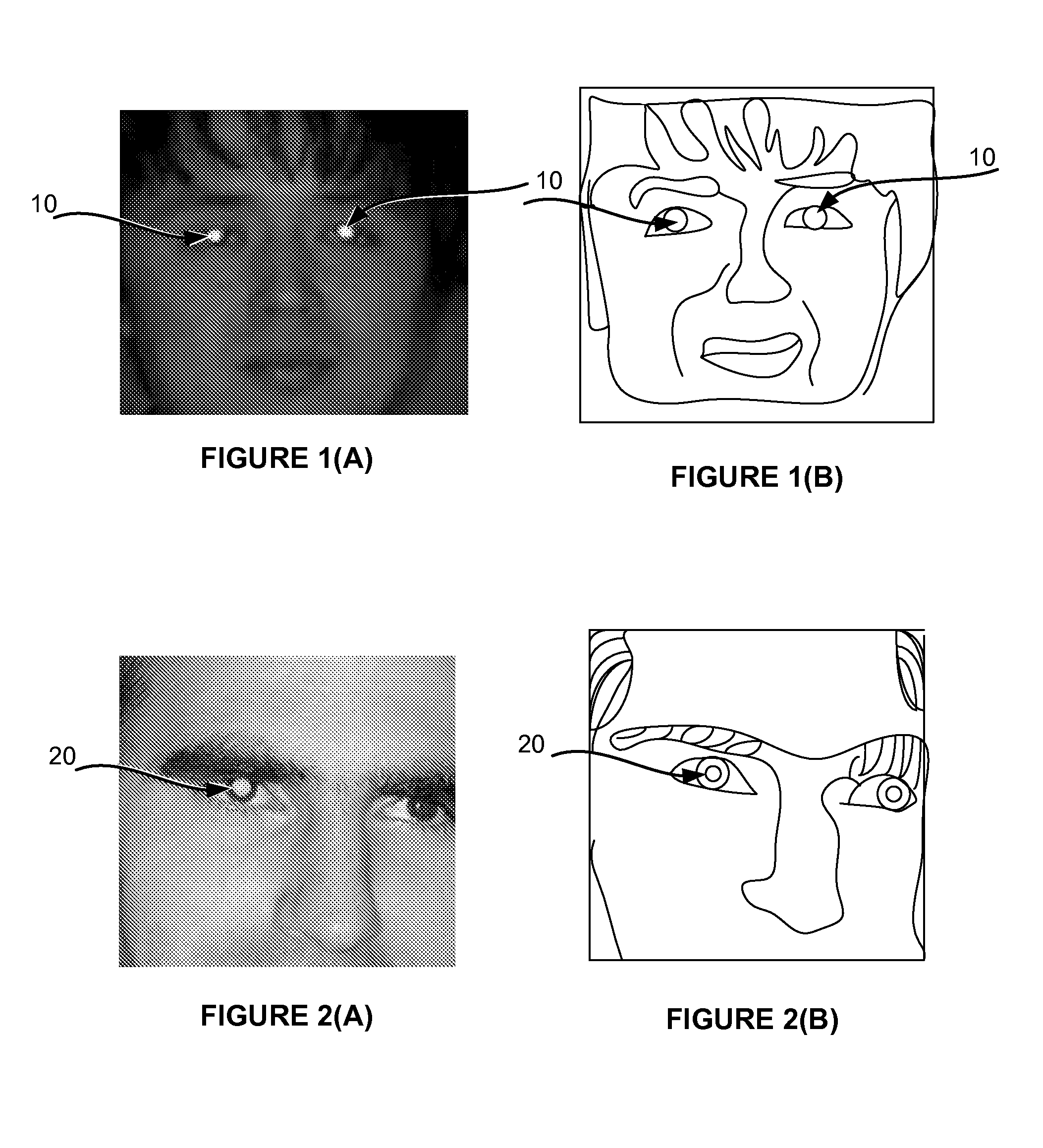
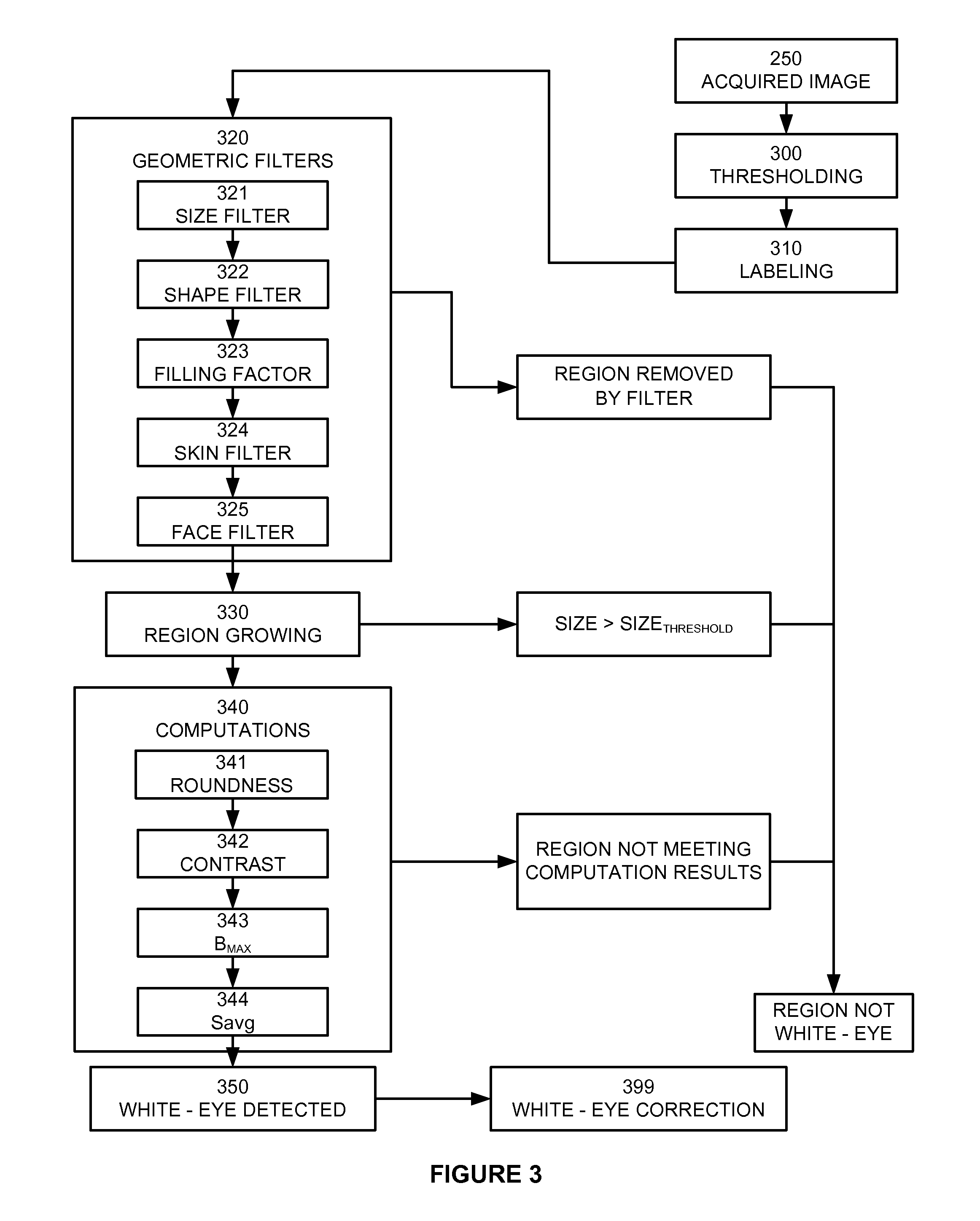
[0037]A method is provided for automatic detection and correction of small white eyes. A flowchart illustrating one embodiment is shown in FIG. 3. In this embodiment, an eye defect is said to be white or golden if it is bright, for example, in Lab color space the local average luminance I is higher than 100, and is not too saturated, for example, in Lab color space, the absolute value of a and b parameters does not exceed 15.

[0038]Initially, the luminance of each pixel of an acquired image 250 to be corrected is determined and a selection of all the pixels whose luminance is larger than a threshold value is made, 300. In the preferred embodiment, the acquired image is in RGB space and the intensity is calculated as I=max[R,G] and the intensity threshold value is 220. Also, to avoid highly-saturated colors (such as pure red or pure green) the saturation computed as abs(R−G) is compared to a threshold of 35, and discarded if higher. As such, only high-luminance pixels are retained, wh...


PUM


Abstract

A technique for detecting large and small non-red eye flash defects in an image is disclosed. The method comprises selecting pixels of the image which have a luminance above a threshold value and labeling neighboring selected pixels as luminous regions. A number of geometrical filters are applied to the luminous regions to remove false candidate luminous regions.

Description

PRIORITY[0001]This application claims the benefit of priority under 35 USC §119 to U.S. provisional patent application No. 60 / 773,714, filed Feb. 14, 2006.BACKGROUND[0002]1. Field of the Invention[0003]The present invention relates to a system and method for automatically detecting and correcting non red-eye flash defects in an image, and in particular, white-eye flash defects.[0004]2. Description of the Related Art[0005]Published PCT patent application no. WO 03 / 071484 A1 to Pixology, discloses a variety of techniques for red-eye detection and correction in digital images. In particular, Pixology discloses detecting “glint” of a red-eye defect and then analyzing the surrounding region to determine the full extent of the eye defect.[0006]U.S. Pat. No. 6,873,743 to Steinberg discloses a similar technique where initial image segmentation is based on both a red chrominance component and a luminance component.[0007]White-eye defects (white eyes) do not present the red hue of the more co...

Claims


Application Information

Patent Timeline
Patent Type & Authority Patents(United States)
IPC IPC(8): G06K9/00
CPCG06K9/0061G06T7/0002G06T7/408G06T7/604G06T2207/20061G06T2207/30216G06T7/90G06T7/64G06V40/193
Inventor CIUC, MIHAINANU, FLORINPETRESCU, STEFANCAPATA, ADRIANVERTAN, CONSTANTINCORCORAN, PETERBIGIOI, PETRONELSTEINBERG, ERAN
Owner FOTONATION LTD
Why Eureka
Try Eureka