Fiducial marker patterns, their automatic detection in images, and applications thereof

a facial marker and automatic detection technology, applied in the field of facial marker detection technology, can solve the problems of not being able to use the scene with motion between different exposures, and achieve the effects of improving visual quality, facilitating easy development, and improving visual quality

Active Publication Date: 2017-08-31
MILLENNIUM THREE TECH
View PDF5 Cites 139 Cited by
  • Summary
  • Abstract
  • Description
  • Claims
  • Application Information

AI Technical Summary

Benefits of technology

[0026]In yet a further aspect of the present invention there is provided an augmented reality implementation of the system wherein the mobile device is a wearable device where the graphics shown on the display are positioned to coincide or correspond to the perceived direction as seen by one or both of the user's eyes (for example the Google Glass® wearable device). In yet a further aspect of the present invention there is provided an augmented reality implementation of the system in an optical see through configuration where the display has controllable transparency so the user can see through the display thus providing the illusion of the web graphic ‘widgets’ appearing in a position that allows the user to associate the widget with the marker, either with the graphic drawn directly over the marker position or elsewhere in the display with some line or arrow or some means of visually associating the widget with the fiducial marker.
[0027]In yet a further aspect of the present invention there is provided a system where the mobile device is a smartphone or tablet where the widgets are drawn on top of the video or still image in positions which are a function of the image location of the fiducial markers in such a way to improve the visual quality of the view. This function would take the position in the display image of all detected fiducial markers as input and would output the location of the widget centers. A line or arrow or some indication may connect the marker location to the widget so that if the widget is not directly close to the fiducial the user would be able to see what fiducial the widget belongs to. Below are three possible elements of this function, the function may perform one, two, or three of these:
[0028]In yet a further aspect of the present invention there is provided a system where the mobile device is a wearable device containing one or two displays visible from one or both of the user's eyes where the widgets are drawn in position so they appear in the same direction as the fiducial markers, so they appear on top of the fiducial markers or are in display positions which are a function of the image location of the fiducial markers in such a way to improve the visual quality of the view. This function would take the position in the display image of all detected fiducial markers a

Problems solved by technology

Attempts to improve this involve “High Dynamic Range” (HDR) imagery which typically combines several images with different exposures, an approach not useful for scenes with motion between these different exposures.

Method used


Image

  • Fiducial marker patterns, their automatic detection in images, and applications thereof
  • Fiducial marker patterns, their automatic detection in images, and applications thereof
  • Fiducial marker patterns, their automatic detection in images, and applications thereof

Examples


Embodiment Construction

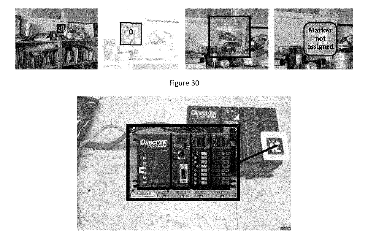
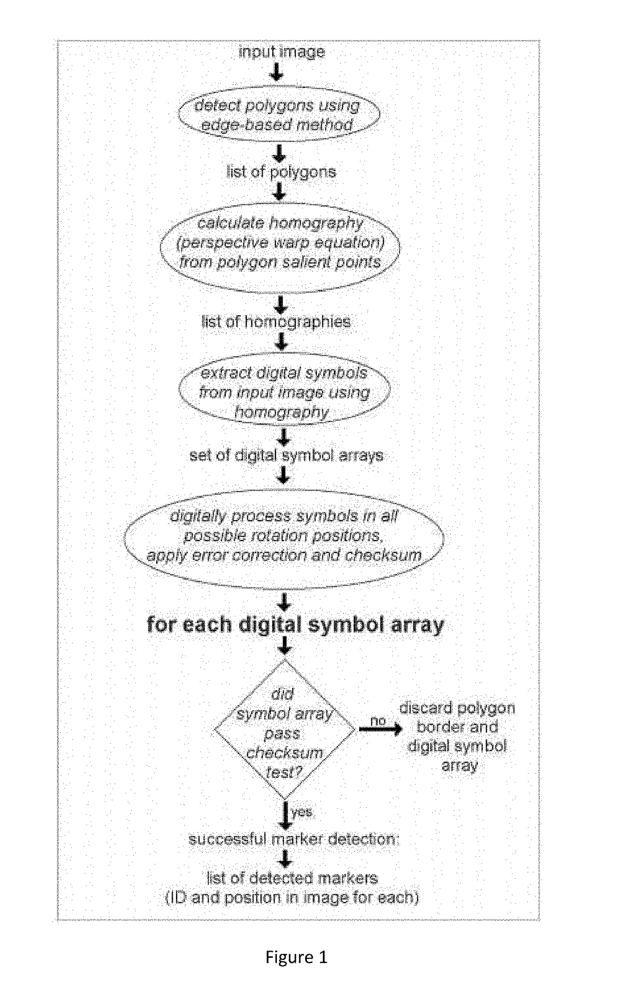
[0134]The present invention discloses a marker detectable by visual means and inventions using the marker(s) for applications including multimedia graphics and industrial visualization. The present invention extends the “Main Detection Algorithm” with unique additions that take advantage of the fact that many applications of the marker detection are a sequence of image “frames”, such as from a video camera, which contain similar content from frame to frame. Subsequent images as in a video stream from a hand-held or wearable device, or video camera on an automated device, are typically the result of camera and object motion but contain a lot of the same objects. The usage of knowledge from previous image frames can be used to achieve superior performance such as to provide faster processing, handle larger images with limited processing power, help estimate the marker position with an image frame when a marker is not detected, and improve the precise image measurements for application...


PUM


Abstract

Fiducial markers are printed patterns detected by algorithms in imagery from image sensors for applications such as automated processes and augmented reality graphics. The present invention sets forth extensions and improvements to detection technology to achieve improved performance, and discloses applications of fiducial markers including multi-camera systems, remote control devices, augmented reality applications for mobile devices, helmet tracking, and weather stations.

Description

TECHNICAL FIELD[0001]The present invention sets forth improvements of fiducial marker detection technology to achieve enhanced performance, and teaches applications of fiducial markers including multi-camera systems, remote control devices, augmented reality applications for mobile devices, helmet tracking, and weather stations.BACKGROUND OF THE INVENTION[0002]Marker patterns can be added to objects or scenes to allow automatic systems to find correspondence between points in the world and points in camera images, and to find correspondences between points in one camera image and points in another camera image. The former has application in positioning, robotics, and augmented reality applications, the latter has application in automatic computer modeling to provide the coordinates of world points for applications of the former. Furthermore, marker patterns can be used to contain information relating to various products. For example, marker patterns printed out and mounted on a piec...

Claims


Application Information

Patent Timeline
IPC IPC(8): G06T7/13G06K9/00A63F13/25G06F17/50A63F13/213A63F13/65G06T7/246G02B27/01
CPCG06T7/13G06T7/246G06K9/00671G02B27/0172G06F17/5009A63F2300/8076A63F13/65A63F13/25G06T2207/20076G02B2027/014G02B2027/0138A63F13/213G02B27/017G02B2027/0187G02B27/0093G06T2207/30204G06T2207/30208G06T7/75G06T7/277G06F30/00G06F30/20G06V20/20
Inventor FIALA, MARK
Owner MILLENNIUM THREE TECH
Why Eureka
Try Eureka