Card flat bar for a carding machine

a carding machine and flat bar technology, applied in the field of carding machine flat bar, can solve the problems of limited technology of ground-down clothing tip grinding, time-consuming and labor-intensive processing, and grinding to a level finish, and achieve the effect of reducing the number of grinding operations

Inactive Publication Date: 2008-03-04
TRUETZSCHLER GMBH & CO KG
View PDF16 Cites 0 Cited by
  • Summary
  • Abstract
  • Description
  • Claims
  • Application Information

AI Technical Summary

Benefits of technology

[0010]Said distance between said sliding surface and a lower surface of the assembled card flat bar may be a distance between said sliding surface and a lower surface of the clothing support portion, or may be a distance between said sliding surface and a further layer or component attached to the clothing support, for example, a distance between the sliding surface and tips of clothing provided on the clothing support. The fixing region may be adjustable in position relative to the carrier element by means, in particular, of there being a separation distance between the fixing region and that part of the carrier element with which it engages, permitting a degree of play between the fixing region and the carrier element.
[0011]Where, in a preferred embodiment, there is a clearance between the outer wall of the fixing region and the inner wall of an opening in the carrier element, the distance between the sliding-contact surface and the card flat tips is uniformly and equally precisely adjustable for each card flat bar, and this distance can be fixed, thus enabling a dimensionally accurate card flat bar to be produced in a simple manner. All manufacturing tolerances of the card flat bar, the clothing and during assembly (including dismantling) can be eliminated. The card flat bar clothed in accordance with the invention advantageously and effectively reduces or prevents an accumulation of tolerances during assembly of the card flat clothing, the technically destructive grinding to a level finish and the decline in accuracy during use. In particular it is an advantage that the measures according to the invention render grading of the card flat bars according to class unnecessary, as a result achieving quite considerable rationalisation. The height dimensions achieved within a card flat set comprising a plurality of card flat bars are identical.
[0015]Advantageously, a flexible clothing is present. The flexible clothing may comprise a backing and clothing tips, wires, hooks or the like. The backing may be in the form of a strip. The clothing may consist of saw-tooth wire strips, e.g. all-steel clothing. The clothing may be secured to the card flat bar in the region of the heel face thereof. The clothing may be secured to the card flat bar by adhesion. Advantageously, the card flat bar and the card flat clothing can be associated with the same reference plane. The reference plane may be a flat counter-surface, e.g. a plate or the like, for the tips of the card flat clothing. The card flat bar may be an extruded profile of light metal, e.g. aluminium. The extruded profile may be a hollow profile. The carrier element may be cut to length, e.g. by sawing. The cut-to-length card flat bar can be straightened. In use, the distance between the sliding-contact surfaces of the card flat heads on the outer face of the slideway and the envelope curve of the card flat clothing tips is uniform. The end parts may be non-releasably connected to the card flat heel. Advantageously, the fixing region of the end head part is fixed in an opening of the carrier element. Advantageously, a distance (degree of play) is present between the fixing region of the end head part and at least partial regions of the inner wall of the opening.

Problems solved by technology

This process takes time and effort.
The technological efficiency of the ground-down clothing tips is limited.
In particular the accumulation of tolerances as the card flat clothing is assembled, the technically destructive grinding to a level finish and the decline in accuracy during use are therefore disadvantageous.
It has become apparent that the weld joints in some cases lead to stresses in the card flat bar and then exchange of the entire card flat bar is necessary.
The drawback of this arrangement is that the drive element acting outside the slideway exerts an undesirable lever action, and hence a bending moment, on the head piece and on the carrier element.
In addition, in this way the head piece does not slide with dimensional accuracy on the slideway, and disruptive tilting can occur.
The manufacture of the carrier element from a steel tube, which is cold-drawn through a profiling mould and subsequently has to be heat-treated, is associated with considerable outlay, both in relation to manufacturing costs and from a technological point of view.
Finally, it is particular disadvantage that the head pieces become worn during in operation.
The effort involved in exchange of the worn head pieces is considerable, since the welded or riveted joints of the head pieces to the carrier element have to be unfastened and then reinstated again after the replacement.
The repair can only be carried out when the carding machine is idle, which leads to considerable disruption to operations and to production losses.

Method used


Image

  • Card flat bar for a carding machine
  • Card flat bar for a carding machine
  • Card flat bar for a carding machine

Examples


Embodiment Construction

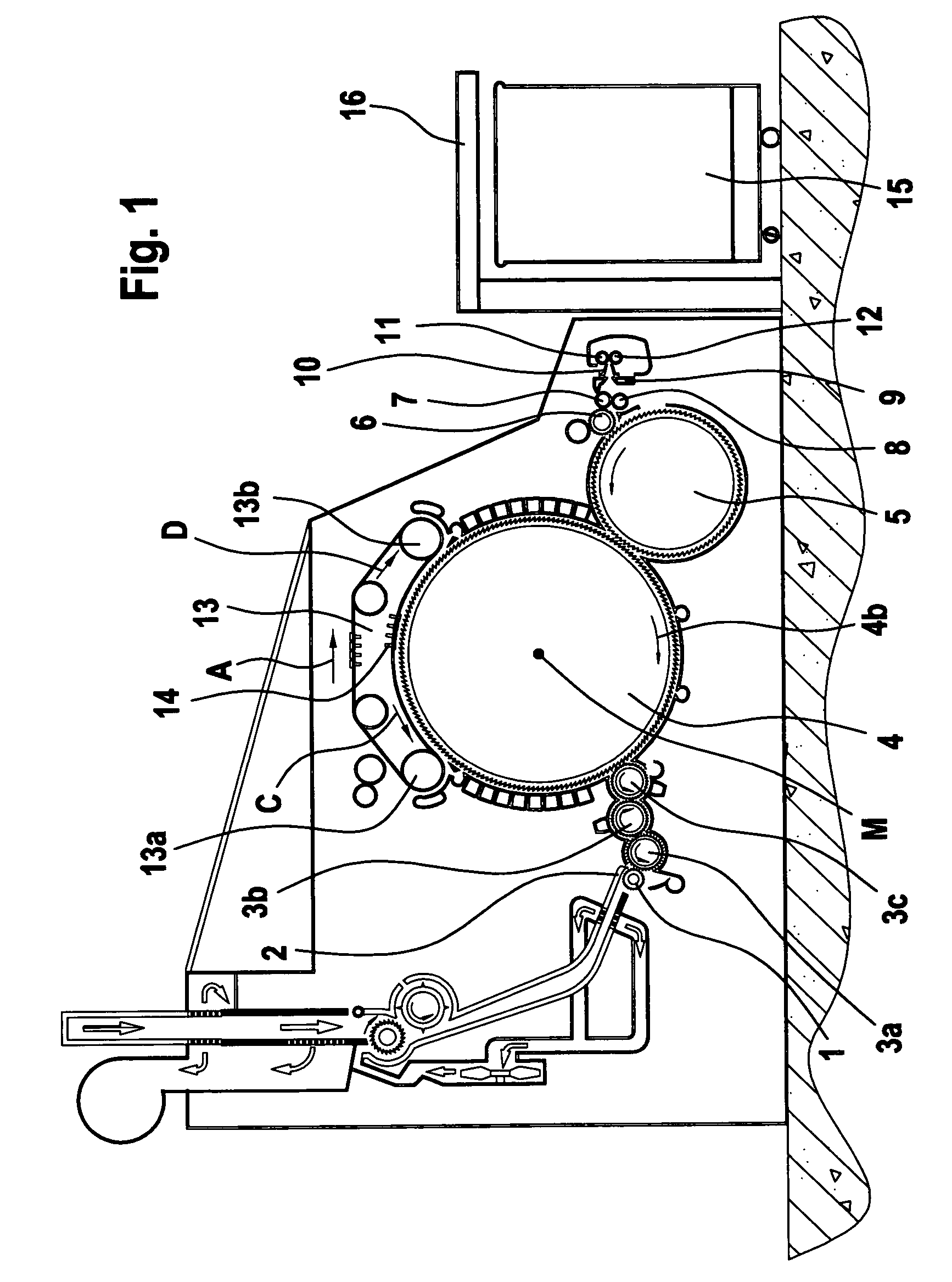
[0030]With reference to FIG. 1, a carding machine, for example, a TC 03 card made by Trutzschler GmbH & Co. KG of Monchengladbach, Germany, has a feed roller 1, feed table 2, licker-ins 3a, 3b, 3c, cylinder 4, doffer 5, stripping roller 6, squeezing rollers 7, 8, web-guide element 9, web funnel 10, take-off rollers 11, 12, revolving card flat 13 with card flat guide rollers 13a, 13b and card flat bars 14, can 15 and can coiler 16. The directions of rotation of the rollers are shown by respective curved arrows. The letter M denotes the midpoint (axis) of the cylinder 4. The reference numeral 4a denotes the clothing and 4b denotes the direction of rotation of the cylinder 4. The letter C denotes the direction of rotation of the revolving card flat 13 in the carding setting and the letter D the return transport direction of the card flat bars 14.

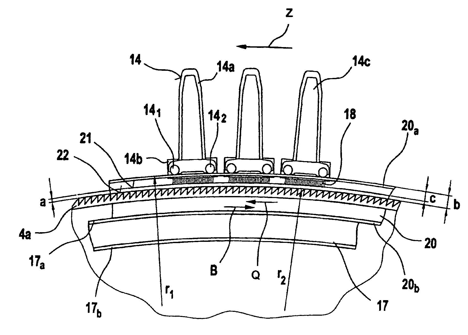
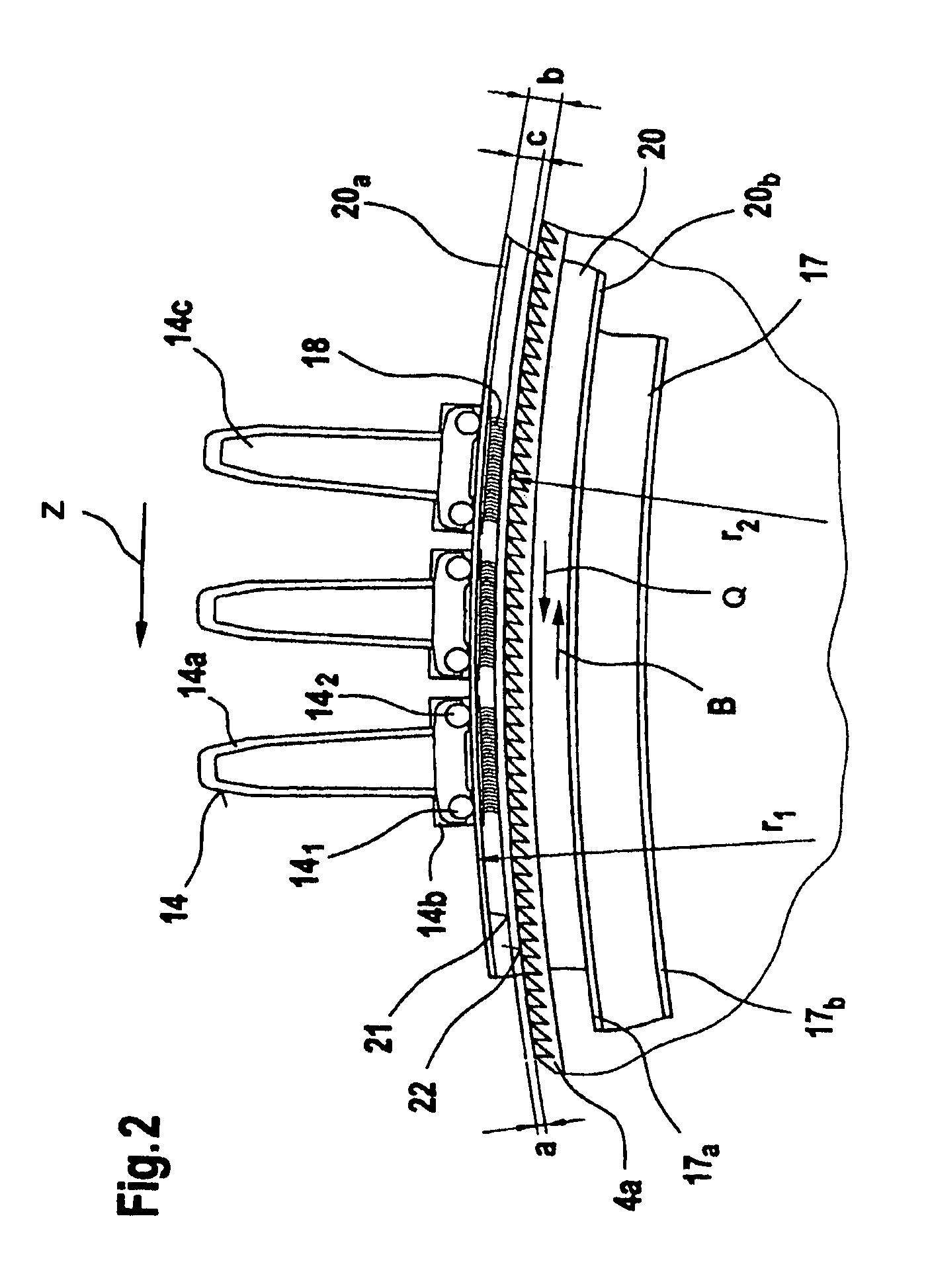
[0031]Referring to FIG. 2, on each side of the carding machine, a flexible bend 17 having several adjusting screws is secured laterally to the...


PUM

PropertyMeasurementUnit
flatnessaaaaaaaaaa
heightaaaaaaaaaa
distanceaaaaaaaaaa

Abstract

A carding machine, includes a carrier element with a clothing support part (card flat heel). Two end head parts are associated with the carrier element. The carrier element and the end head parts form at least three assembled components, and the end head parts comprise at least one sliding-contact region, which is in contact with the slideway, and at least one fixing region, which is fixed to the carrier element and at the same time holds the sliding-contact region. Between the fixing region of the end head part and at least partial regions of the carrier element there is a distance (clearance), and the distance between the lower limit of the sliding contact region and the card flat heel and / or the free tips of the clothing is adjustable and fixable.

Description

CROSS REFERENCE TO RELATED APPLICATION[0001]This application claims priority from German Patent Application No. 103 58 257.6, dated Dec. 11, 2003, the entire disclosure of which is incorporated herein by reference.BACKGROUND OF THE INVENTION[0002]The invention relates to a card flat bar for a carding machine, which card flat bar comprises a carrier element with a clothing support part, and two end head parts associated with the carrier element.[0003]In a known card top bar, the carrier element and the end head parts form at least three assembled components, and the end head parts comprise at least one sliding-contact region, which is in contact with the slideway, and at least one fixing region, which is fixed to the carrier element and at the same time holds the sliding-contact region.[0004]Modern card flat bars are extruded from aluminium. In practice, the extruded card flat bar is cut to length and finished, for example, to a flatness of 0.05 mm. Carrier pins are then adhesively s...

Claims


Application Information

Patent Timeline
Patent Type & Authority Patents(United States)
IPC IPC(8): D01G15/08D01G15/24
CPCD01G15/24
Inventor SCHNITZLER, JURGEN
Owner TRUETZSCHLER GMBH & CO KG
Why Eureka
Try Eureka