Sliding table for workbench

a workbench and sliding technology, applied in the field of sliding tables, can solve the problems of increasing instability of the table, affecting the stability of the cantilevered portion, and affecting the stability of the tabl

Inactive Publication Date: 2008-03-04
SMITH DARRIN EUGENE
View PDF22 Cites 12 Cited by
  • Summary
  • Abstract
  • Description
  • Claims
  • Application Information

AI Technical Summary

Problems solved by technology

However the table become increasing unstable as the path lengthens.
The cantilevered portion is not supported and for that reason is relatively unstable.
Any weight on the table may cause the workbench to tip over or may cause the table to bend or fracture.

Method used


Image

  • Sliding table for workbench
  • Sliding table for workbench
  • Sliding table for workbench

Examples


Embodiment Construction

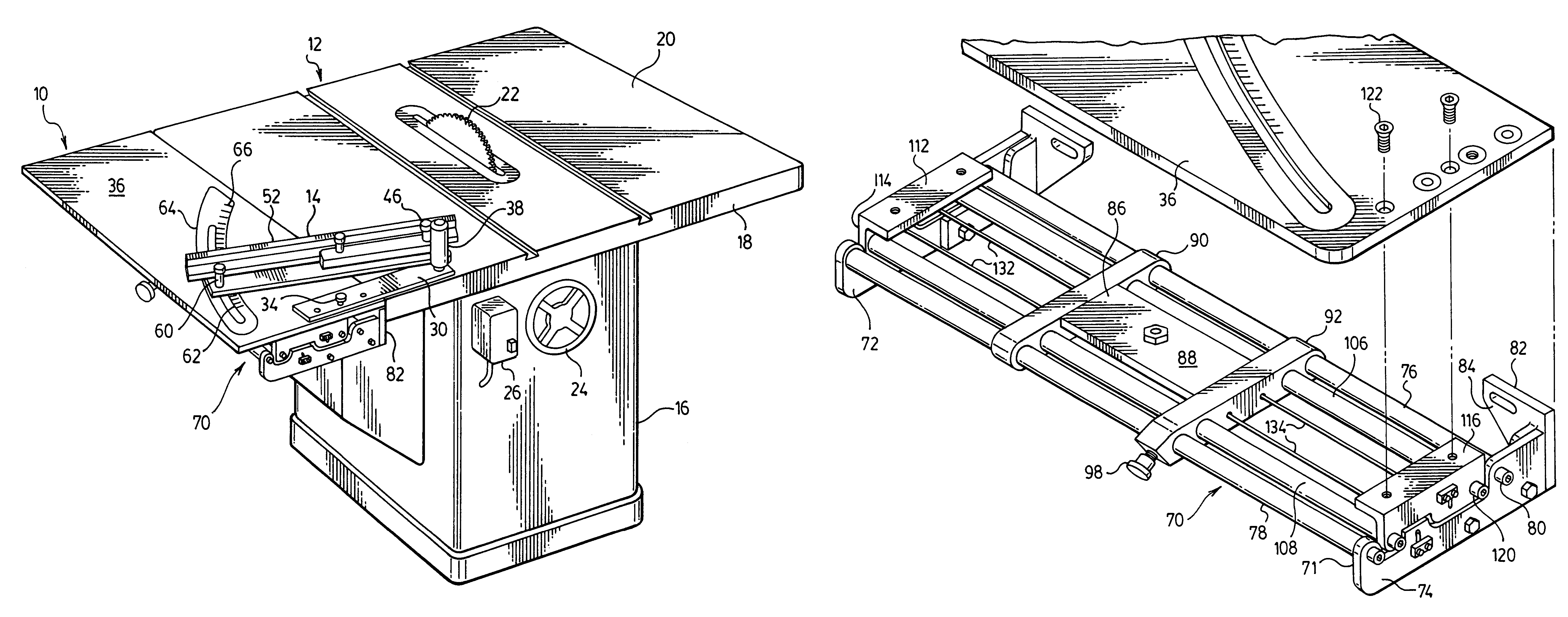
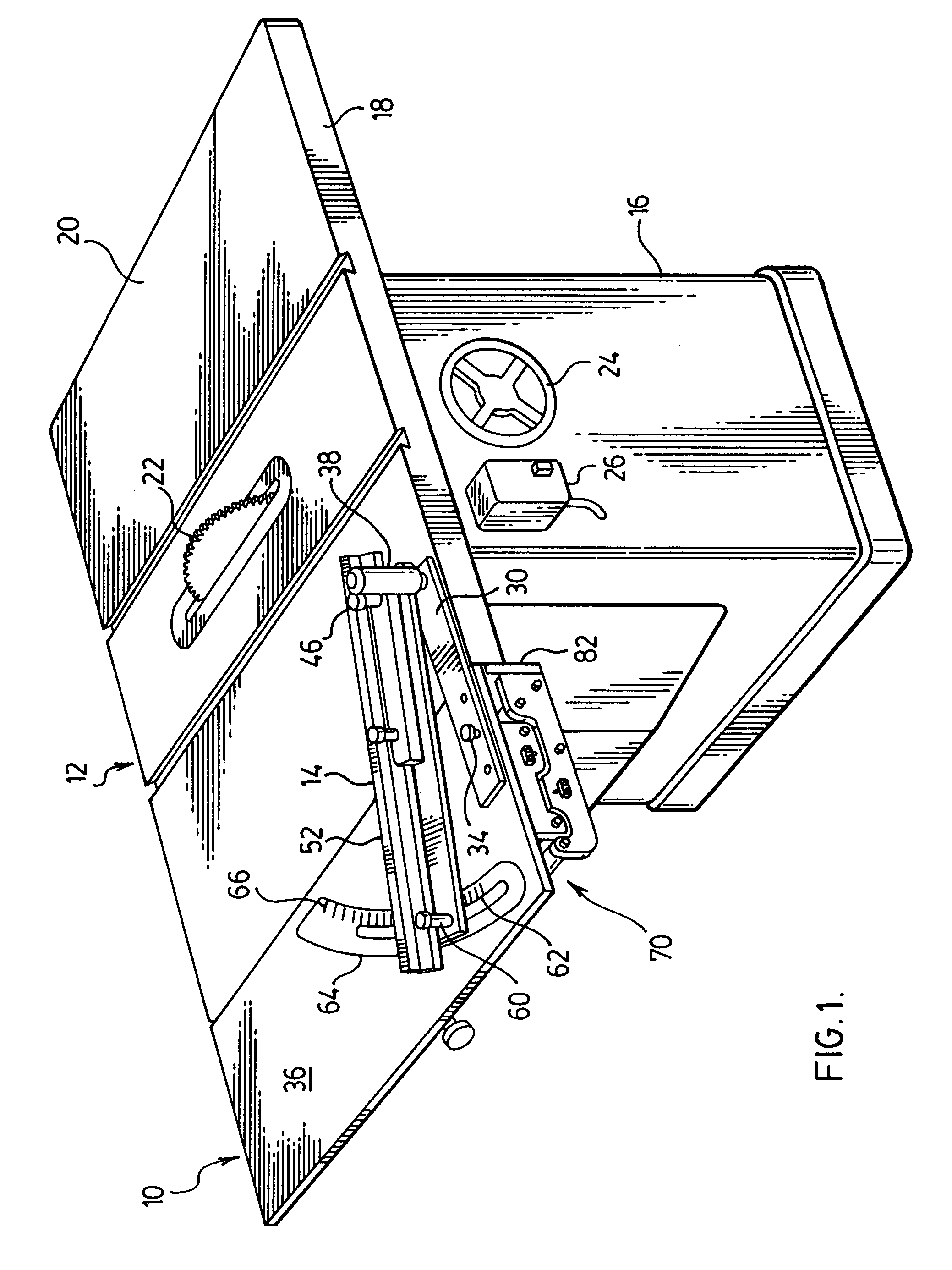
[0021]With reference to FIG. 1, the sliding table of the invention, generally 10, is shown in conjunction with a power saw unit, generally 12, and a guide 14 for a piece of work or stock. The power saw unit is conventional and consists of a housing 16 and an upper wall 18 having a working surface 20 through which a circular saw blade 22 projects. A circular handle 24 for adjusting the level of the saw blade extends from the side wall of the housing as does an electrical box 26 having an on-off switch.

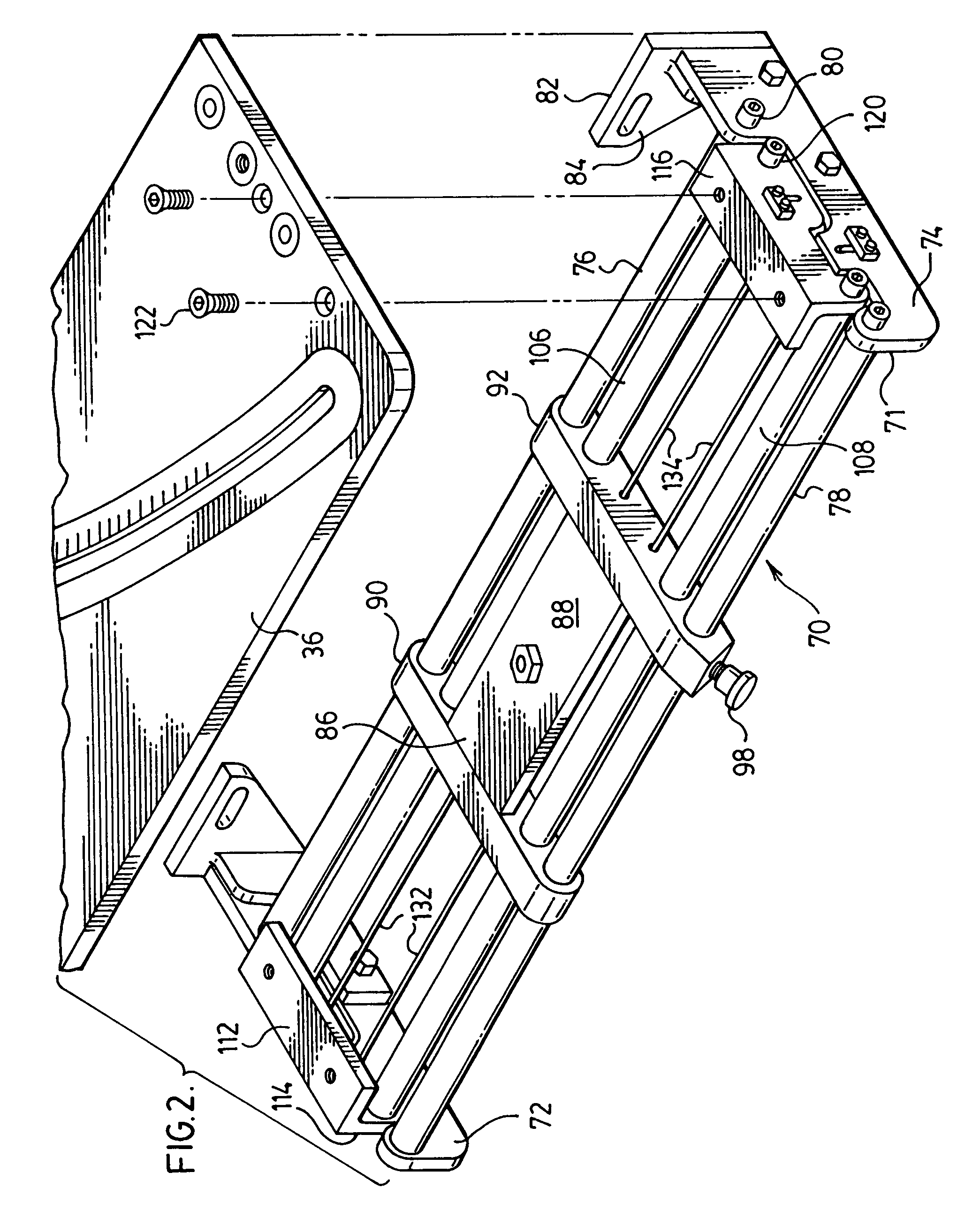
[0022]With reference to FIGS. 1 and 3, the guide has base plate 30 having, adjacent to one end, a number of threaded openings 32 through which a threaded pin 34 extends. Threaded openings are also formed in the upper panel 36 of the sliding table for receipt of the pin. The base plate thus can be attached at various preselected positions on the sliding table.

[0023]A handle 38 is connected to the base plate adjacent to the end opposite openings 32 to facilitate rotating of the base plate...


PUM

PropertyMeasurementUnit
distanceaaaaaaaaaa
movementaaaaaaaaaa
weightaaaaaaaaaa

Abstract

The sliding table is used in conjunction with a workbench and includes a panel slidable along a path which is disposed normal to the longitudinal axis of the workbench. The panel has stop points in front and behind the workbench. At each stop point, the panel has an outwardly extending portion which is cantilevered from an outer support and an inwardly extending portion which is prevented from rising by an inner support. Both supports are beneath the panel and are spaced apart from one another.

Description

[0001]This Non-provisional application claims priority under 35 U.S.C. § 119(a) on Patent Application No(s). 2,436,301 filed in Canada on Jul. 31, 2003, the entire contents of which are hereby incorporated by reference.FIELD OF THE INVENTION[0002]This invention relates to sliding tables for workbenches such as benches, worktables or any surface that is used for doing mechanical or practical work such as is found on a power saw unit, a router, a drill press and so on. More particularly the invention relates to a sliding table having means for accurately guiding the movement of the table and improved means for supporting a piece of work or stock on the sliding table.BACKGROUND OF THE INVENTION[0003]Sliding tables for workbenches are known for providing lateral support to a piece of work or stock in front of or behind the workbench. Such tables usually travel on a path which is perpendicular to the longitudinal axis of the workbench. The path extends from in front of the workbench to b...

Claims


Application Information

Patent Timeline
Patent Type & Authority Patents(United States)
IPC IPC(8): B26D7/06B23D47/02B27G5/02
CPCB23D47/025B27G5/023Y10T83/6608Y10T83/858Y10T83/7647Y10T83/727Y10T83/773Y10T83/6614Y10T83/6609
Inventor SMITH, DARRIN EUGENE
Owner SMITH DARRIN EUGENE
Why Eureka
Try Eureka