
Optical and electrical blending of display images

a display image and optical blending technology, applied in the field of optical and electrical blending of display images, to achieve the effect of facilitating installation, alignment and maintenance of the system, and high quality

Inactive Publication Date: 2008-03-04
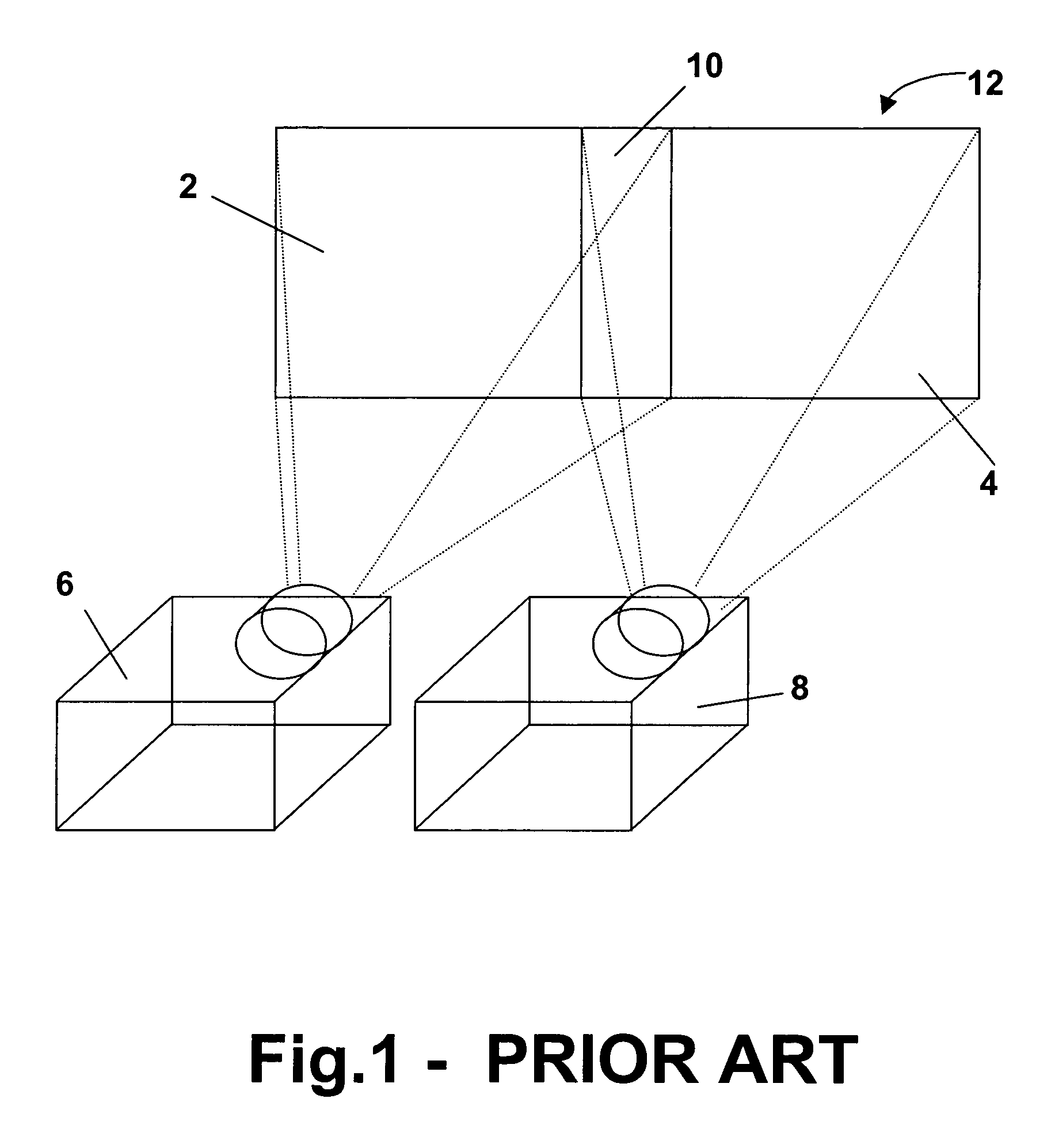
BARCO NV
View PDF11 Cites 42 Cited by
  • Summary
  • Abstract
  • Description
  • Claims
  • Application Information

AI Technical Summary

Benefits of technology

[0015]It is an object of the present invention to overcome the above mentioned problems in order to obtain a system and a method providing a high quality resulting image combined with a facilitated installation, alignment and maintenance of the system.

Problems solved by technology

Quality of the optical soft edge means, such as transmission curve, shape and lifetime, and accuracy of electrical soft edge means are limitations on each of the blending methods to obtain a result which combines the best of both blending methods.

Method used


Image

  • Optical and electrical blending of display images
  • Optical and electrical blending of display images
  • Optical and electrical blending of display images

Examples


first embodiment

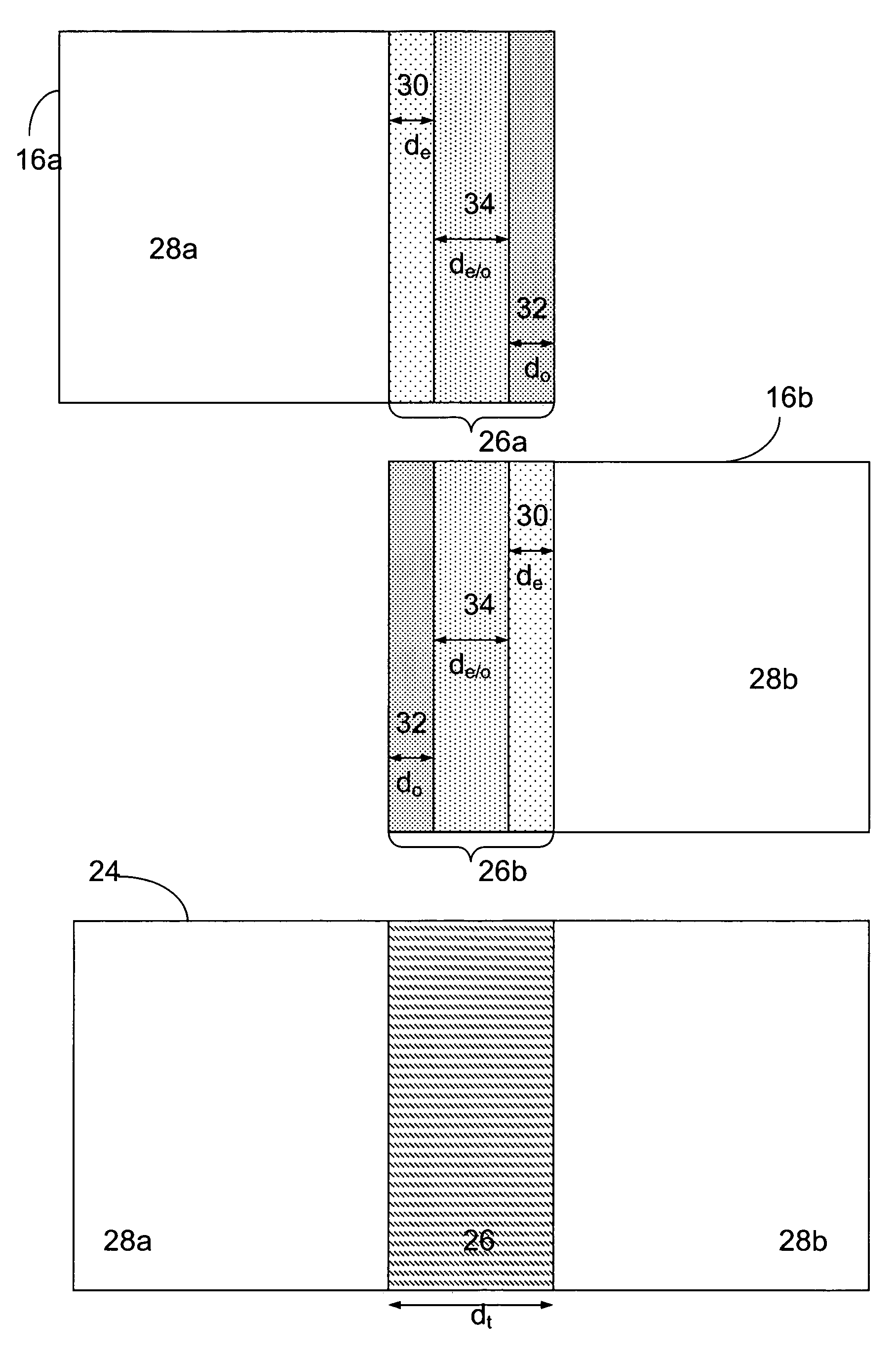
[0049]According to the present invention, for every sub-image 16a, 16b, the blending area 26a, 26b can be divided into three different spatial regions. A first of those spatial regions is first region 30, which is located in the blending area 26a, 26b of the first sub-image 16a, 16b adjacent to the non-overlapping area 28a, 28b of the respective sub-image 16a, 16b. The light intensity in the first region 30 is attenuated using only electrical attenuation, which is an electronically driven intensity attenuation.

[0050]First region 30 has a width de. In the current description, this type of attenuation will be referred to as active electrical attenuation. A second of the spatial regions is second region 32, which is located at the edge of sub-image 16a, 16b, i.e. at the part of the blending area 26a, 26b of the sub-image 16a, 16b which is located away from the non-overlapping area 28a, 28b. In the second region 32, the light intensity is attenuated using optical attenuation. Second reg...

second embodiment

[0069]A second embodiment describes a blending method according to the present invention, whereby the extent of the area where optical blending is active is limited. Such systems have an optical attenuation of each single projection device, that is only active on the image in a second half or less of the blending area 26a. This can be expressed by the equation

de / o+do≦50%  [6]

[0070]Systems, where the optical blending satisfies this equation, have the major advantage that they can be switched from blended mode to non-blended mode using only electrical control of the images without applying mechanical articulation of optical masks.

[0071]By using optical blending only in the second half or less of the blending areas 26a, 26b, it is possible to change the electrical attenuation function from a ramp to a step function with a transmission of 100% in the first half of the blending area 26a, 26b and 0% in the second half of the blending area 26a, 26b. Two sub-images 16a, 16b edge blended usi...


PUM


Abstract

A method and a device for soft edge blending of projected display images (16a, 16b) is provided. The method combines optical and electrical soft edge blending in an blending area (26) by using electrical blending in one fraction (146a, 146b) of the blending area (26a, 26b) of two or more overlapping images and using optical blending in another fraction (144a, 144b) of the blending area (26a, 26b). The method according to the present invention overcomes problems with manufacturing, alignment and adjustment of optical masks (148a, 148b) used in optical blending and the difficulties with electrically blending black images. The blending method can also be used in systems providing switching from soft edge blending to hard edge matching.

Description

TECHNICAL FIELD OF THE INVENTION[0001]The present invention relates to a method for blending tiled images displayed by a projection display system. In particular it relates to a method for obtaining improved blending of tiled images displayed by a projection display system. The method provides both a good black level blending and a high flexibility.BACKGROUND OF THE INVENTION[0002]When tiling sub-images of a tiled image, hard edge or soft edge techniques can be applied.[0003]Where hard edge techniques are applied, the projected sub-images are put next to each other. This is often not an optimal solution because the edges between the sub-images are difficult to arrange in perfect alignment and the join may well be noticeable.[0004]Where soft edge techniques are applied, an overlap area is created in which two or more neighbouring sub-images, i.e. at least a first sub-image and second sub-image, are blended so that there is at least a gradual transition from the first sub-image to the...

Claims


Application Information

Patent Timeline
Patent Type & Authority Patents(United States)
IPC IPC(8): H04N9/12G03B21/13H04N5/74
CPCG03B21/13H04N9/3147
Inventor MATTHYS, GEERTMAXIMUS, BARTDEVOS, GLENN
Owner BARCO NV
Learn More