
Pulsed signal device characterization employing adaptive nulling and IF gating

a technology of pulsed signal and characterization, which is applied in the direction of resistance/reactance/impedence, instruments, transmission monitoring, etc., can solve the problems of narrowband vnas that are typically limited in terms of pulse width and narrowband vnas limited, so as to facilitate the measurement of dut performance

Active Publication Date: 2008-03-04
KEYSIGHT TECH
View PDF7 Cites 12 Cited by
  • Summary
  • Abstract
  • Description
  • Claims
  • Application Information

AI Technical Summary

Benefits of technology

The present invention provides an adaptive nulling receiver channel that uses an adaptive nulling filter to filter out targeted frequency components in a pulsed signal. The filter has adjustable nulls that can be adjusted to correspond to a vicinity of a targeted frequency component. This filtered pulsed signal is then used to measure the performance parameters of a device under test (DUT) in a pulsed signal environment. The technical effect of this invention is to provide a more accurate and reliable method for measuring the performance of DUTs in a pulsed signal environment.

Problems solved by technology

Unfortunately, broadband VNAs are typically limited in terms of a minimum pulse width by an ultimate bandwidth performance (e.g., receiver rise-time, detector / ADC speed, etc.) that is achievable given the performance, availability and cost of broadband receiver components.
On the other hand, while typically having less stringent requirements for receiver component performance than broadband VNAs, narrowband VNAs are limited to a minimum PRF by a stopband performance limit of a bandpass filter used in processing the received signal pulses.

Method used


Image

  • Pulsed signal device characterization employing adaptive nulling and IF gating
  • Pulsed signal device characterization employing adaptive nulling and IF gating
  • Pulsed signal device characterization employing adaptive nulling and IF gating

Examples


Embodiment Construction

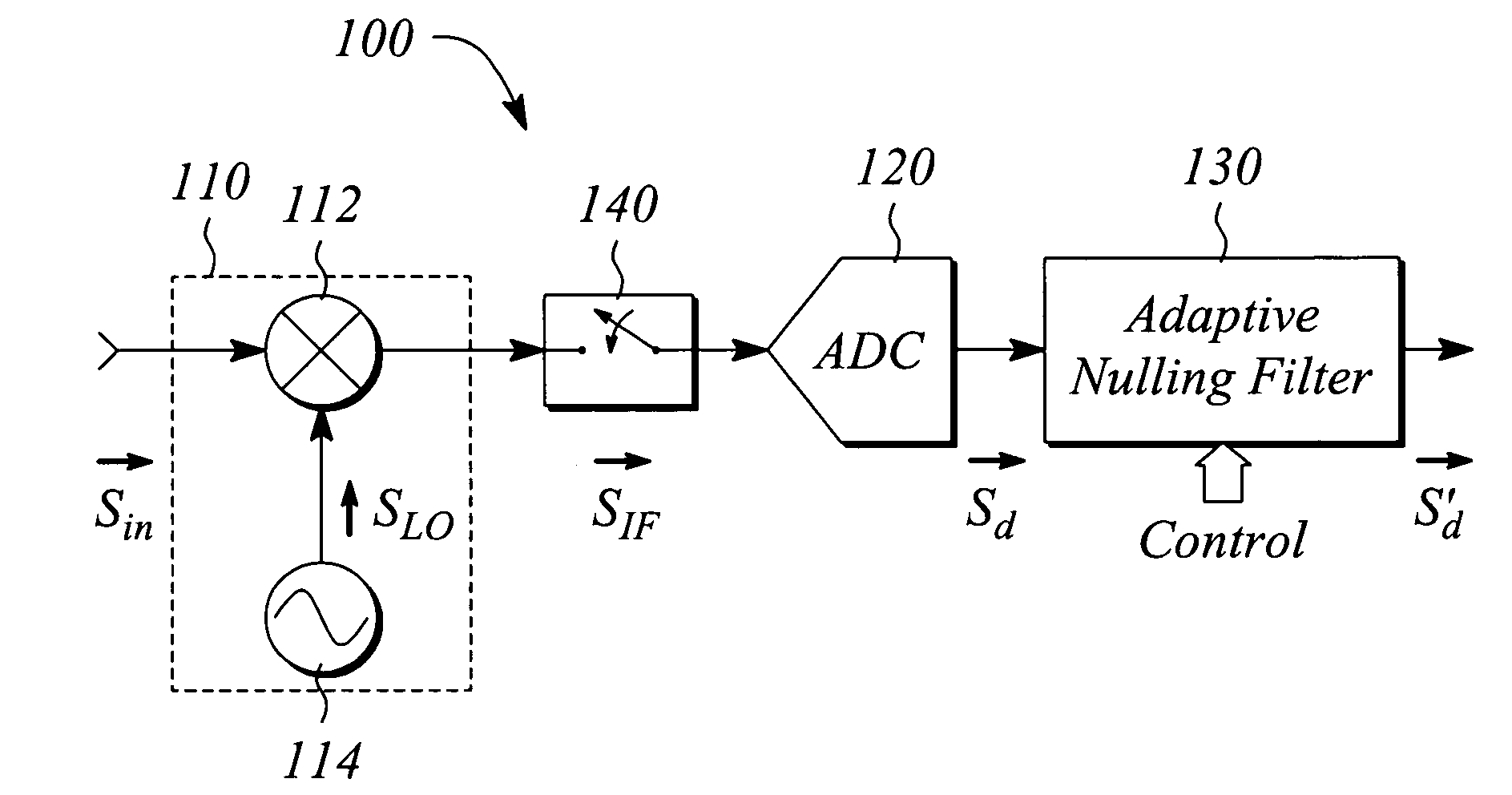
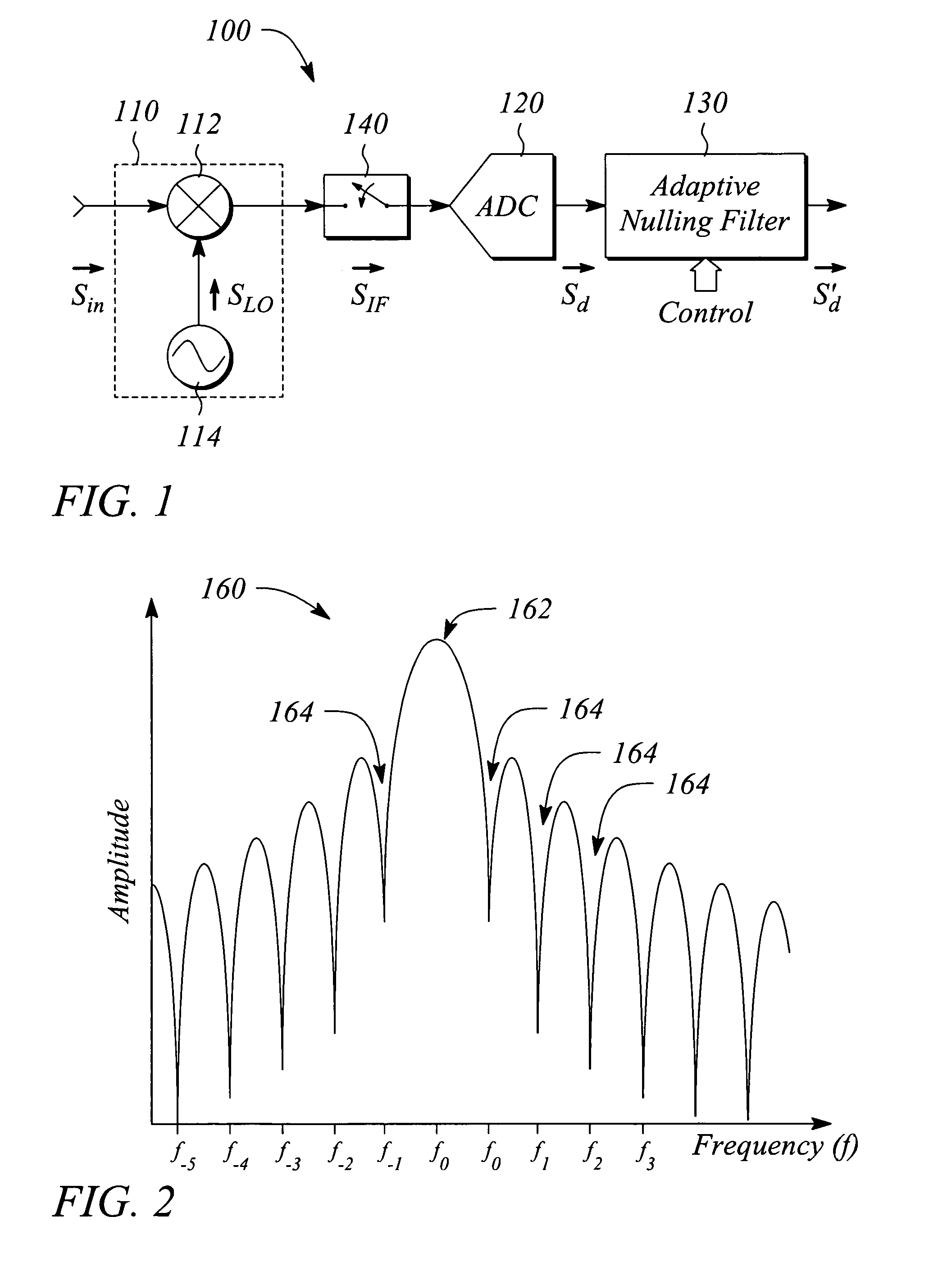
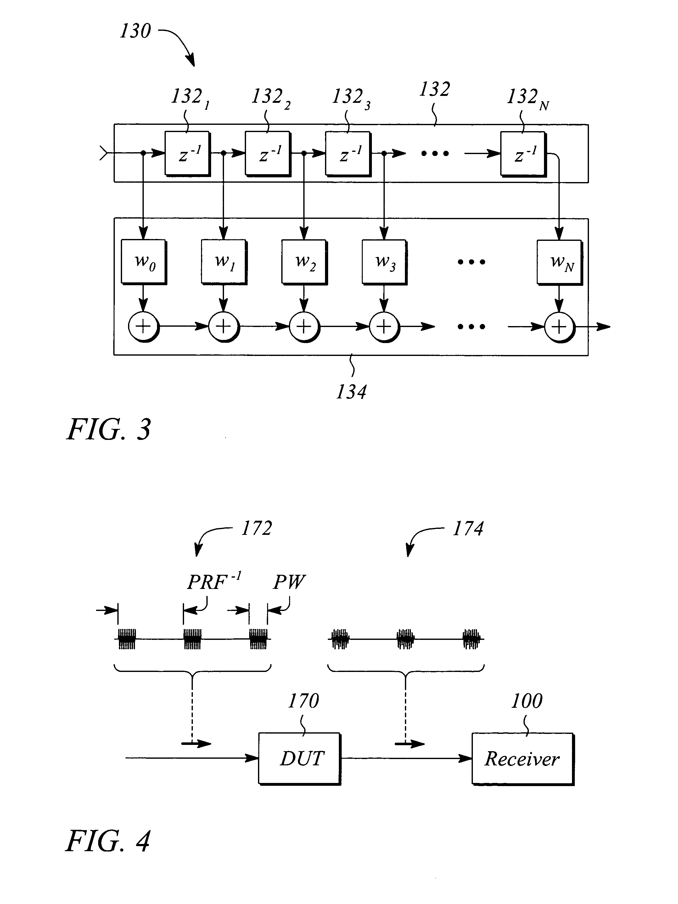
[0022]Various embodiments of present invention facilitate measuring performance parameters for a device under test (DUT) in a pulsed signal environment. In some embodiments, adaptive nulling is employed to reduce effects of harmonics of a pulse modulated (i.e., ‘pulsed’) signal received from the DUT that is operated or tested in the pulsed environment. In some embodiments, the adaptive nulling is employed to substantially eliminate or remove such effects. In particular, filter transmission nulls are adapted to frequencies of targeted signal components including, but not limited to, unwanted or undesired frequency harmonics, thereby reducing an effect of the components. The received pulsed signal provides data from which the measured parameters of the DUT may be determined. The received pulsed signal is essentially free of the effects of the targeted components or harmonics as a result of the adaptive nulling. In some embodiments, intermediate frequency (IF) gating is used in additio...


PUM


Abstract

A receiver channel, test system and method employ adaptive nulling to filter a targeted frequency component from a pulsed signal to produce a filtered pulsed signal. The filtered pulsed signal facilitates measuring pulsed performance parameters of a device under test. The receiver channel includes an adaptive nulling filter having a frequency response with a null that is adjustable in a null location to correspond to a vicinity of the targeted component. The test system includes a pulsed signal source, a test set, and a controller that controls the signal source and the test set. The test set includes the receiver channel with the adaptive nulling filter. The method of adaptive null filtering includes adjusting a location of a null in a frequency response of the adaptive nulling filter to correspond to a vicinity of the targeted component to produce the filtered pulsed signal.

Description

BACKGROUND[0001]Vector network analyzers (VNAs) measure performance characteristics of a device under test (DUT) in terms of S-parameters. In particular, the VNA applies a radio frequency (RF) stimulus signal to one or more ports of the DUT and measures one or more of a reflected response and a transmitted response at each of the DUT ports. The VNA then employs a comparison of the applied RF stimulus signal to the measured responses to calculate the S-parameters for the DUT. The S-parameters, typically determined as a function of frequency, characterize a performance of the DUT.[0002]Traditionally, VNAs often employed a continuous wave (CW) signal as the applied RF signal. As such, the VNA essentially measured a CW response of the DUT and produced S-parameters from the measured CW response. While CW stimulus signals and / or CW measurements may be acceptable in many cases, for some situations a pulse modulated (i.e., ‘pulsed’) applied RF stimulus signal and / or a pulsed measurement of ...

Claims


Application Information

Patent Timeline
Patent Type & Authority Patents(United States)
IPC IPC(8): H04B17/00
CPCG01R27/32
Inventor SHOULDERS, ROBERT E.BETTS, LOREN C.
Owner KEYSIGHT TECH
Learn More