Inflatable mattress assembly

a technology of inflatable mattresses and assembly parts, which is applied in the field of inflatable mattresses, can solve the problems of unattractive, uncomfortable and/or unattractive inflatable mattresses, unattractive and uncomfortable deformation and creasing of the top frame,

Active Publication Date: 2008-04-08
SUN PLEASURE
View PDF75 Cites 42 Cited by
  • Summary
  • Abstract
  • Description
  • Claims
  • Application Information

AI Technical Summary

Benefits of technology

[0008]The top panel has a plurality of elongated, upwardly extending projections which create a variable-height support surface to provide increased support and comfort. The peripheral frame forms a border for the support surface and may have a vertical height approximately the same as the support projections on the top panel. The top panel forms a portion of the peripheral frame to provide a contiguous support surface. The peripheral frame provides increased comfort to the user by giving extra support and cushioning in an area that frequently gives when the weight of a head is placed thereon. For additional comfort, the top corner areas of the mattress may be seamless.
[0009]The peripheral frame is secured along two parallel seams so that it is immovable and not subject to undesirable deformation or creasing. The immovable peripheral frame provides increased comfort as compared to other support structures such as a prior frame fixedly secured along only one seam because the peripheral frame will not crease or undesirably deform when the user places his / her head or other body part thereon. The peripheral frame is in fluid communication with the remainder of the mattress such that the mattress may be inflated from a single inflation valve.
[0011]The inflatable mattress assembly also has support structures inside the main mattress body that are attached to the interior surface of the bottom panel and extend to the interior surface of the top panel. The support structures prevent the top and bottom panels from bowing when inflated and allow the mattress body to form the shape of a traditional mattress.

Problems solved by technology

However, prior inflatable mattresses were found by many people to be uncomfortable and / or unattractive.
The disadvantage with this device is that the top frame is sealed to the bottom frame along a single seam that is substantially interior of the outermost edge of the top frame.
While this construction gives the appearance that the upper layer is separate from and lying above the bottom layer it results in unattractive and uncomfortable deformation and creasing of the top frame.

Method used


Image

  • Inflatable mattress assembly
  • Inflatable mattress assembly
  • Inflatable mattress assembly

Examples


Embodiment Construction

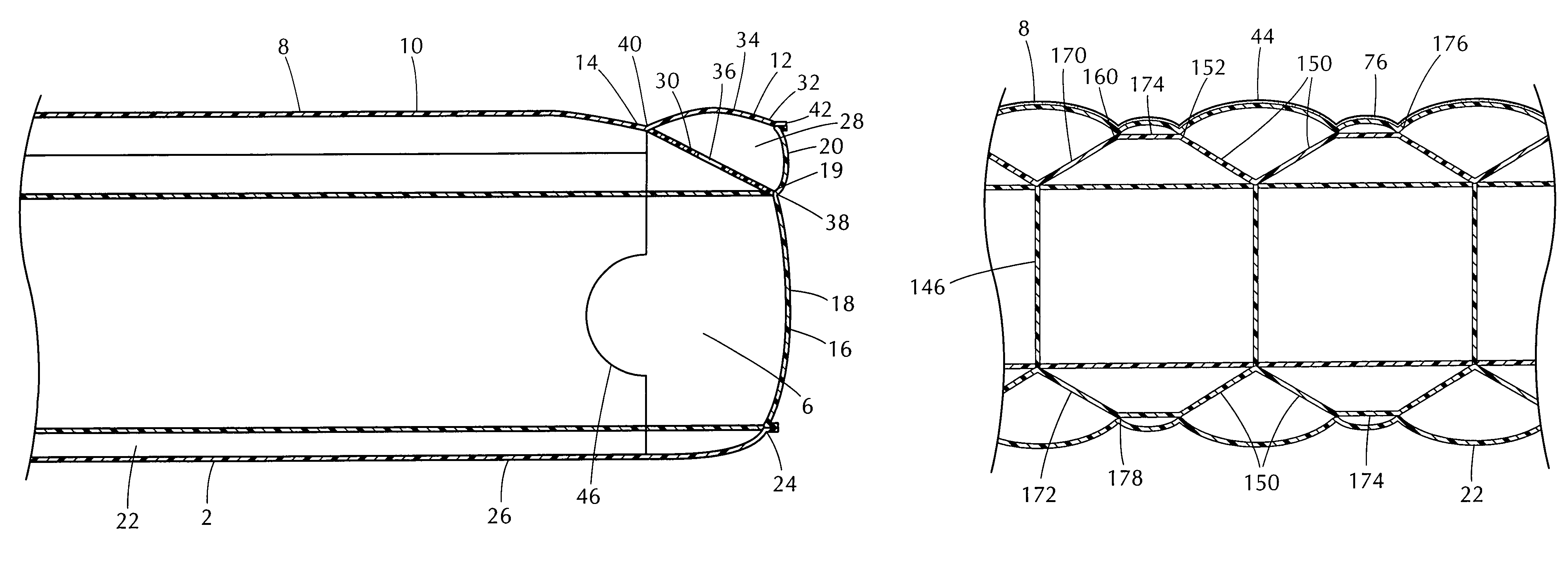
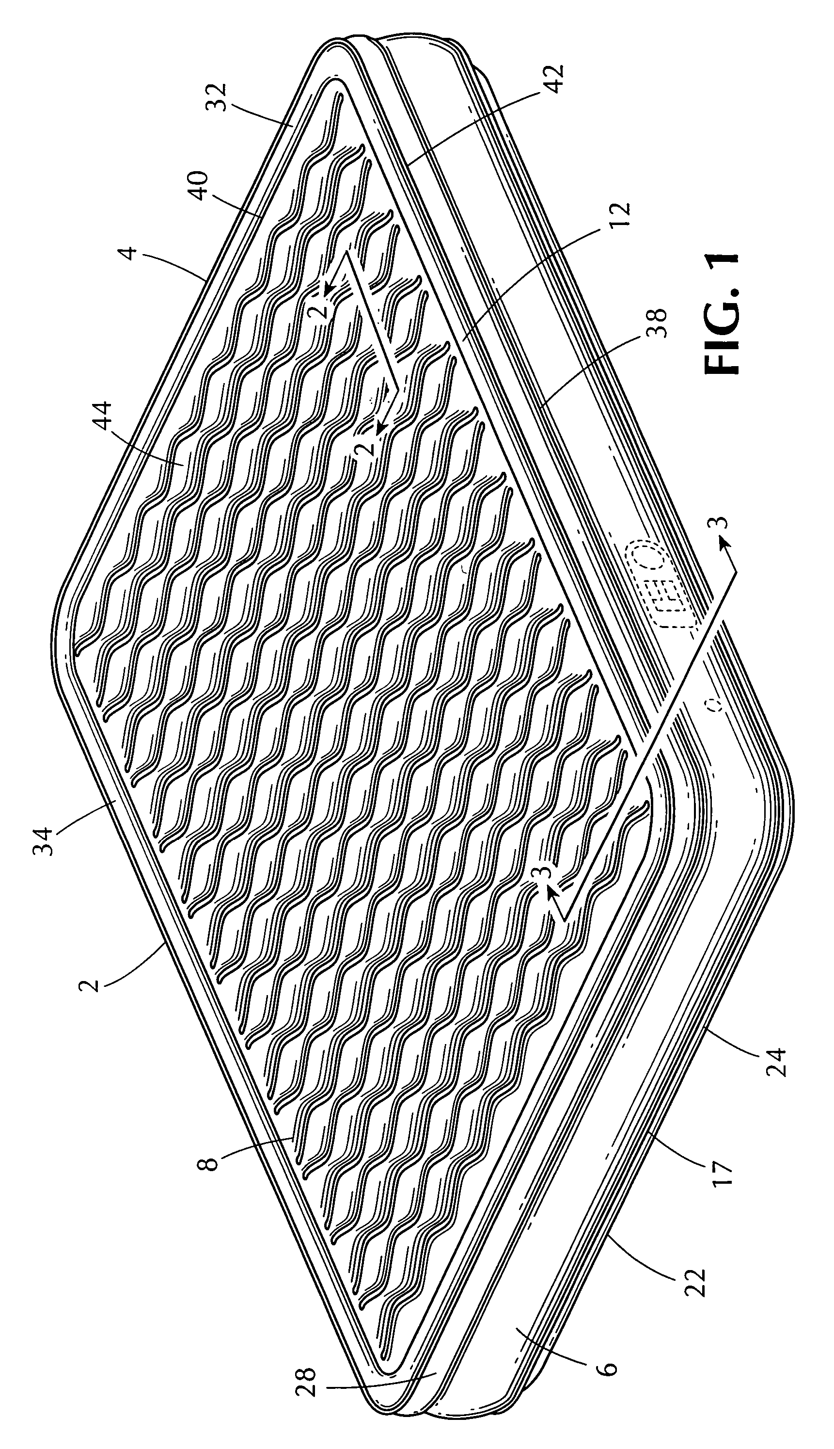
[0017]With particular reference to the drawings, the present invention is directed to an improved inflatable mattress assembly 2. Referring to FIG. 1, the mattress assembly 2 may be in a standard mattress size such as twin, full, queen, and king, or any other suitable size or shape. The inflatable mattress has a top panel 8, bottom panel 22, peripheral side panel 16, and peripheral frame 28 forming a main mattress body 4. The panels and peripheral frame may be composed of rubber, plastic or other materials well known in the art. The panels and peripheral frame 28 may be attached together by heat or by other sealing methods well known in the art.

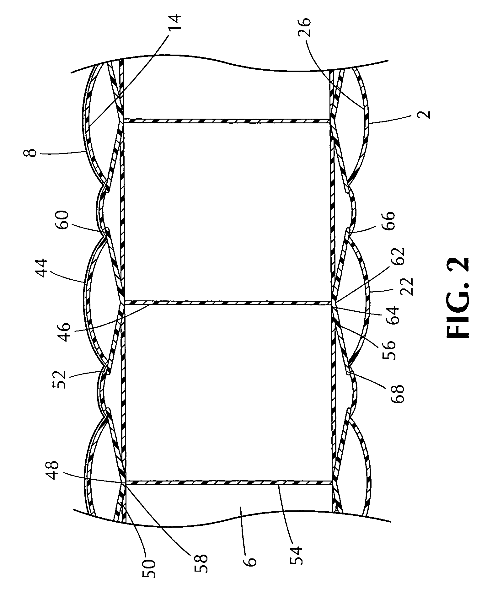
[0018]Referring to FIGS. 2-3, the peripheral side panel 16 may be an integral piece of material or may consist of several pieces arranged in a contiguous loop. A bottom edge 17 of the side panel 16 is connected to a peripheral edge 24 of the bottom panel 22.

[0019]The peripheral frame 28 forms an upper tubular periphery of the inflatable mattr...


PUM


Abstract

An inflatable mattress assembly having a peripheral frame disposed around an upper periphery of the mattress forming an upper tubular periphery that provides a contiguous support surface. The peripheral frame is secured along two seams so that it is flat, smooth, and immovable. The seam where the peripheral frame is connected to the side layer creates a circumferential, horizontal indentation or groove giving the mattress an appearance that mimics a traditional two-layered pillow-top mattress. The components of the inflatable mattress assembly are in fluid communication with each other.

Description

FIELD OF THE INVENTION[0001]The invention pertains to the field of inflatable mattresses.BACKGROUND OF THE INVENTION[0002]Inflatable air mattresses are popular because they are portable and have a relatively low cost compared to traditional mattresses. Further, inflatable air mattress designs have been developed to mimic the appearance and comfort provided by traditional two-layered, pillow-top mattresses. However, prior inflatable mattresses were found by many people to be uncomfortable and / or unattractive.[0003]For instance, U.S. Pat. No. 6,076,214 by Klimenko discloses an inflatable mattress having top and bottom layers and having top and bottom peripheral frames wrapped around each layer. The disadvantage with this device is that the top frame is sealed to the bottom frame along a single seam that is substantially interior of the outermost edge of the top frame. While this construction gives the appearance that the upper layer is separate from and lying above the bottom layer it...

Claims


Application Information

Patent Timeline
Patent Type & Authority Patents(United States)
IPC IPC(8): A47C27/08A47C27/10
CPCA47C27/081A47C27/087
Inventor LAU, VINCENT W. S.
Owner SUN PLEASURE
Why Eureka
Try Eureka