
Vehicle communication system

a technology of vehicle communication and communication system, applied in the field of vehicle communication system, can solve the problems of enormous and achieve the effect of minimizing dsrc interference, minimizing dsrc interference and backend calculations

Inactive Publication Date: 2008-04-08
NISSAN MOTOR CO LTD
View PDF4 Cites 27 Cited by
  • Summary
  • Abstract
  • Description
  • Claims
  • Application Information

AI Technical Summary

Benefits of technology

The present invention provides a vehicle communication system that minimizes interference and backend calculations. The system includes a host vehicle two way communication device, an omni-directional antenna, a bi-directional antenna, a vehicle positioning component, a vehicle map component, and a vehicle broadcast power modulating component. The omni-directional antenna conducts short range communications in the host vehicle broadcast area, while the bi-directional antenna conducts short range communications in the broadcast area and can be selectively aimed based on road data. The vehicle positioning component determines the host vehicle position, and the vehicle map component includes road data with roads being classified by at least one of a road segment attribute. The bi-directional antenna aiming component is configured to aim the bi-directional antenna based on at least one of traffic information received by the host vehicle two way communication device and the road segment attribute of the road on which the host vehicle is traveling on. The technical effects of the invention include minimized interference and backend calculations, improved communication reliability, and improved vehicle safety and efficiency.

Problems solved by technology

In a multi-lane highway scenario, the DSRC interference and backend calculations could be enormous given the extreme amount of information that could eventually be communicated between vehicles.

Method used


Image

  • Vehicle communication system
  • Vehicle communication system
  • Vehicle communication system

Examples


Embodiment Construction

[0030]Selected embodiments of the present invention will now be explained with reference to the drawings. It will be apparent to those skilled in the art from this disclosure that the following descriptions of the embodiments of the present invention are provided for illustration only and not for the purpose of limiting the invention as defined by the appended claims and their equivalents.

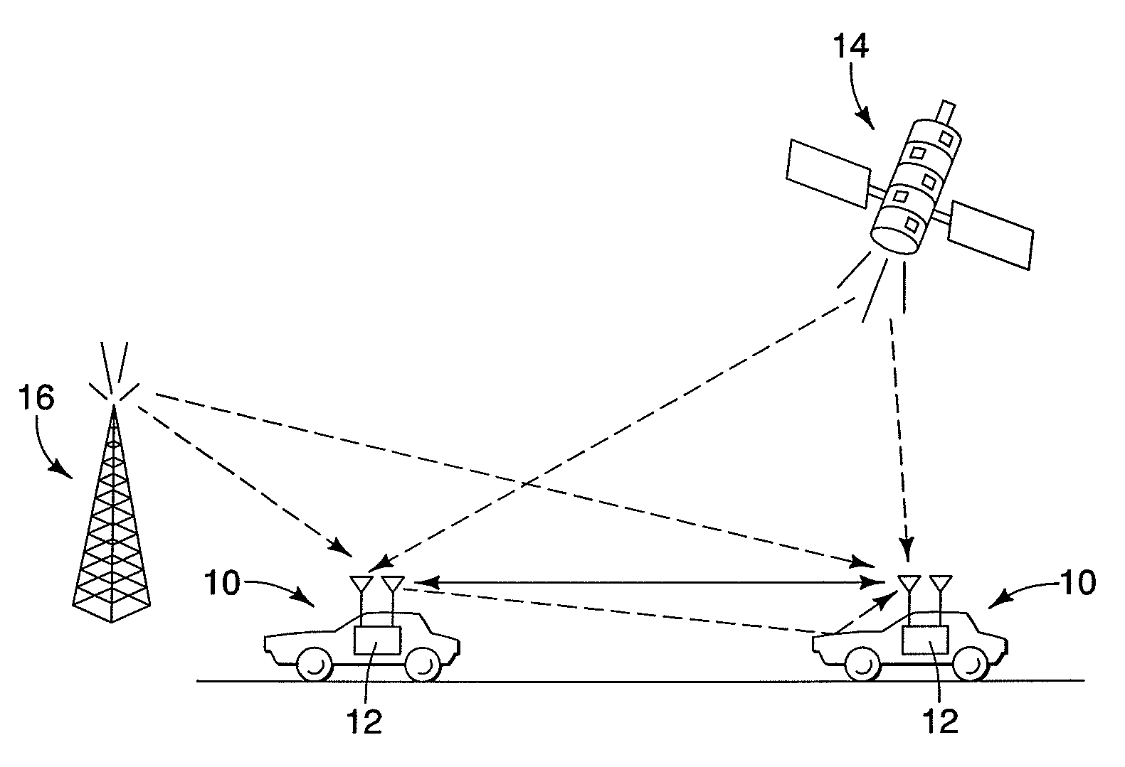
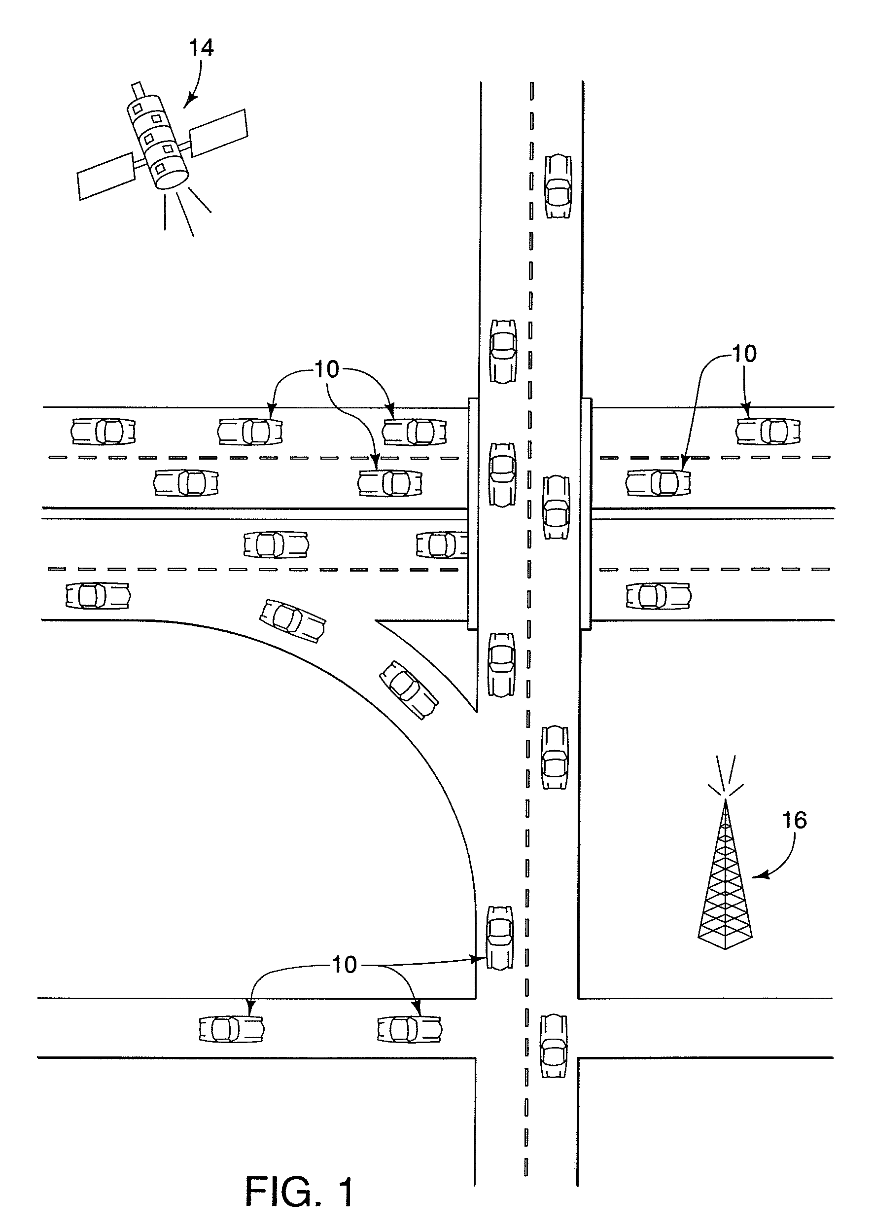
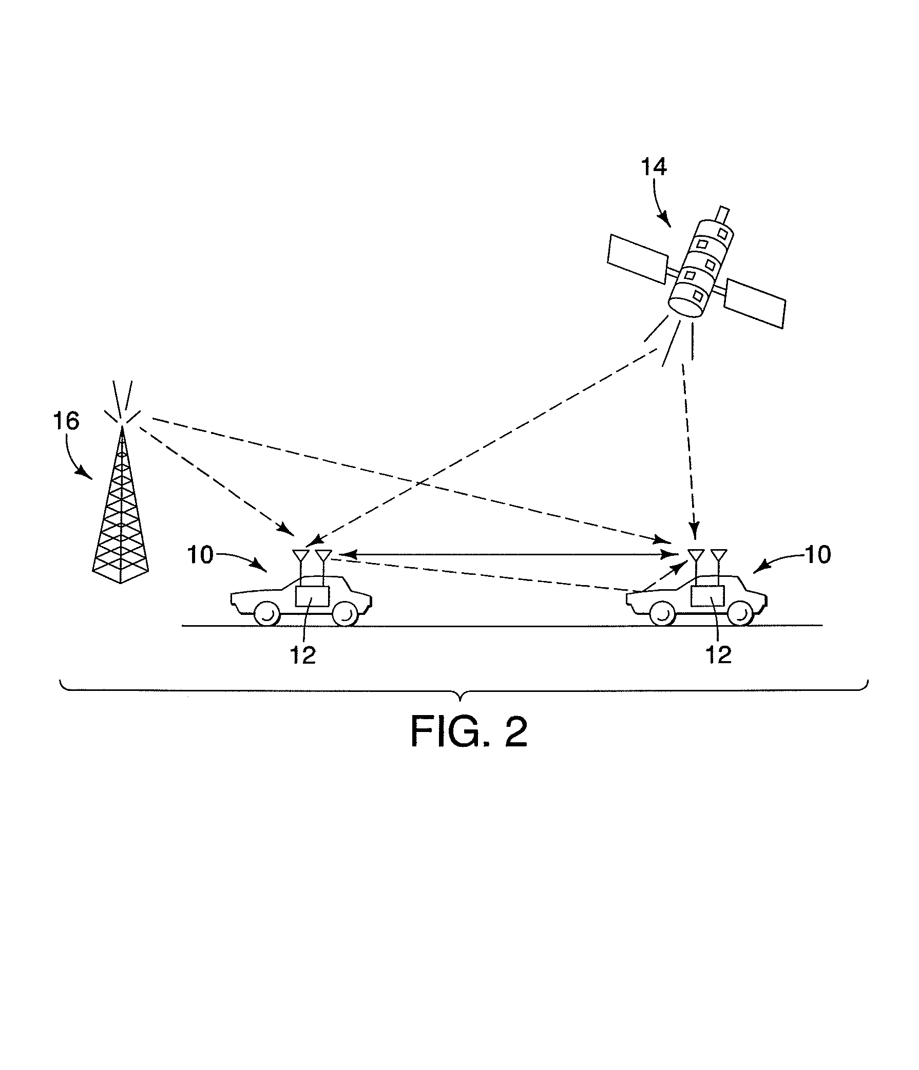
[0031]Referring initially to FIGS. 1 and 2, a two-way wireless communications network is illustrated in which a plurality of vehicles 10 that are each equipped with a vehicle communication system (on-board unit) 12 in accordance with one embodiment of the present invention. The two-way wireless communications network also includes one or more global positioning satellites 14 (only one shown) and one or more roadside units 16 (only one shown) that send and receive signals to and from the vehicles 10. In the preferred embodiment, the on-board units 12 of the vehicles 10 are preferably a dedicated sho...


PUM


Abstract

A vehicle communication system is provide with a host vehicle two way communication device, an omni-directional antenna, a bi-directional antenna, a vehicle positioning component, a vehicle map component and at least one of a vehicle broadcast power modulating component and a bi-directional antenna aiming component. The vehicle map component includes road data with roads being classified by at least one of a road segment attribute. The vehicle broadcast power modulating component selectively varies broadcast power of the omni-directional antenna and broadcast power of the bi-directional antenna based on a road segment attribute of a road on which the host vehicle is traveling on as determined by the vehicle positioning component. The bi-directional antenna aiming component aims the bi-directional antenna based on at least one of traffic information received by the communication device and the road segment attribute of the road on which the host vehicle is traveling on.

Description

BACKGROUND OF THE INVENTION[0001]1. Field of the Invention[0002]The present invention generally relates to a vehicle communication system for direct communication between vehicles. More specifically, the present invention relates to a vehicle communication system that uses an omni-directional antenna and a bi-directional antenna to assist the driver obtain road information.[0003]2. Background Information[0004]Recently, vehicles are being equipped with a variety of informational systems such as navigation systems, Sirius and XM satellite radio systems, the so-called CLARUS weather information system, two-way satellite services, built-in cell phones, DVD players and the like. These systems are sometimes interconnected for increased functionality. Various informational systems have been proposed that use wireless communications between vehicles and between infrastructures, such as roadside units. These wireless communication systems have a wide range of applications ranging from crash ...

Claims


Application Information

Patent Timeline
Patent Type & Authority Patents(United States)
IPC IPC(8): G08G1/09
CPCG08G1/0962H01Q1/3233
Inventor TENGLER, STEVEHEFT, RONALD
Owner NISSAN MOTOR CO LTD
Learn More