Non-lethal cargo projectile

a cargo and projectile technology, applied in the field of non-lethal cargo projectiles and cargo projectiles, can solve the problems of single parachute used as the primary decelerator not providing as much reliability as dual parachutes, and conventional non-lethal applications deliver non-lethal payloads using regular projectile cargo shells. , to achieve the effect of reducing the ejection for

Inactive Publication Date: 2008-04-22
UNITED STATES OF AMERICA THE AS REPRESENTED BY THE SEC OF THE ARMY
View PDF6 Cites 35 Cited by
  • Summary
  • Abstract
  • Description
  • Claims
  • Application Information

AI Technical Summary

Benefits of technology

[0009]Still another object of the invention is to provide a non-lethal projectile that minimizes the ejection force on the contents of the projectile.
[0010]Yet another object of the invention is to provide a non-lethal projectile with a decelerator that is more reliable than a single parachute.

Problems solved by technology

However, conventional non-lethal applications deliver non-lethal payloads using regular projectile cargo shells that descend at high speed with a significant weight and a lethal kinetic energy.
A problem arises when delivering the payload with conventional munition shells, which impact the ground with a full impact velocity that is converted to lethal kinetic energy.
The single parachute used as the primary decelerator does not provide as much reliability as dual parachutes.

Method used


Image

  • Non-lethal cargo projectile
  • Non-lethal cargo projectile
  • Non-lethal cargo projectile

Examples


Embodiment Construction

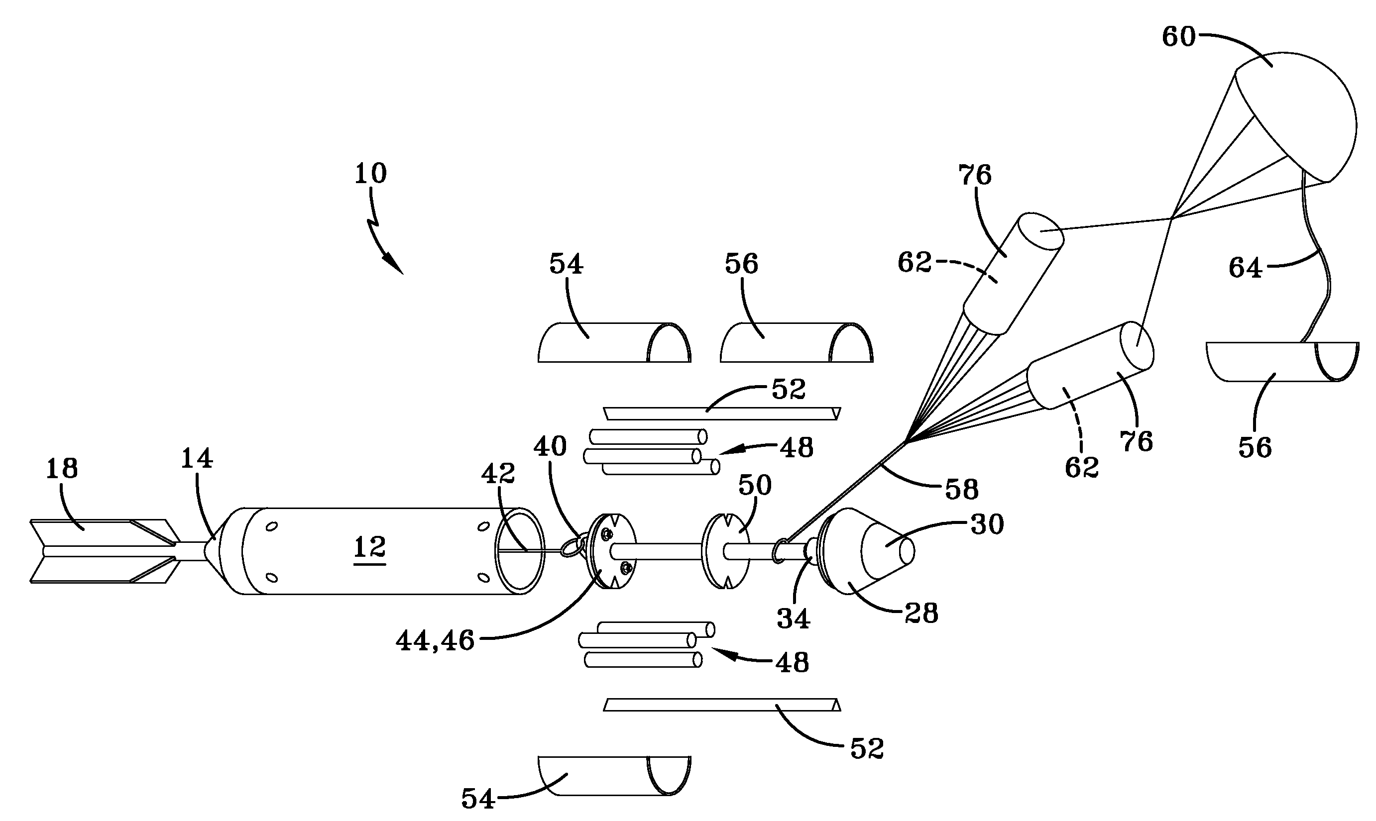
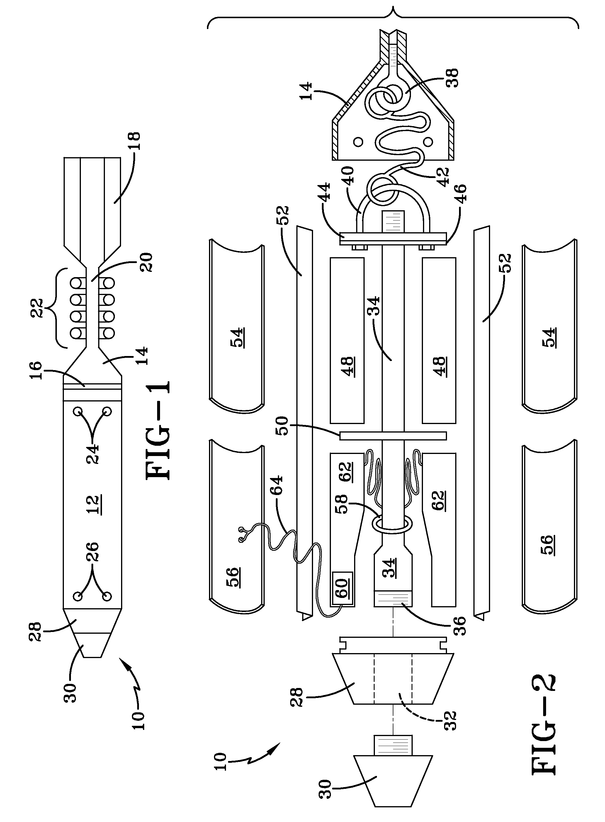
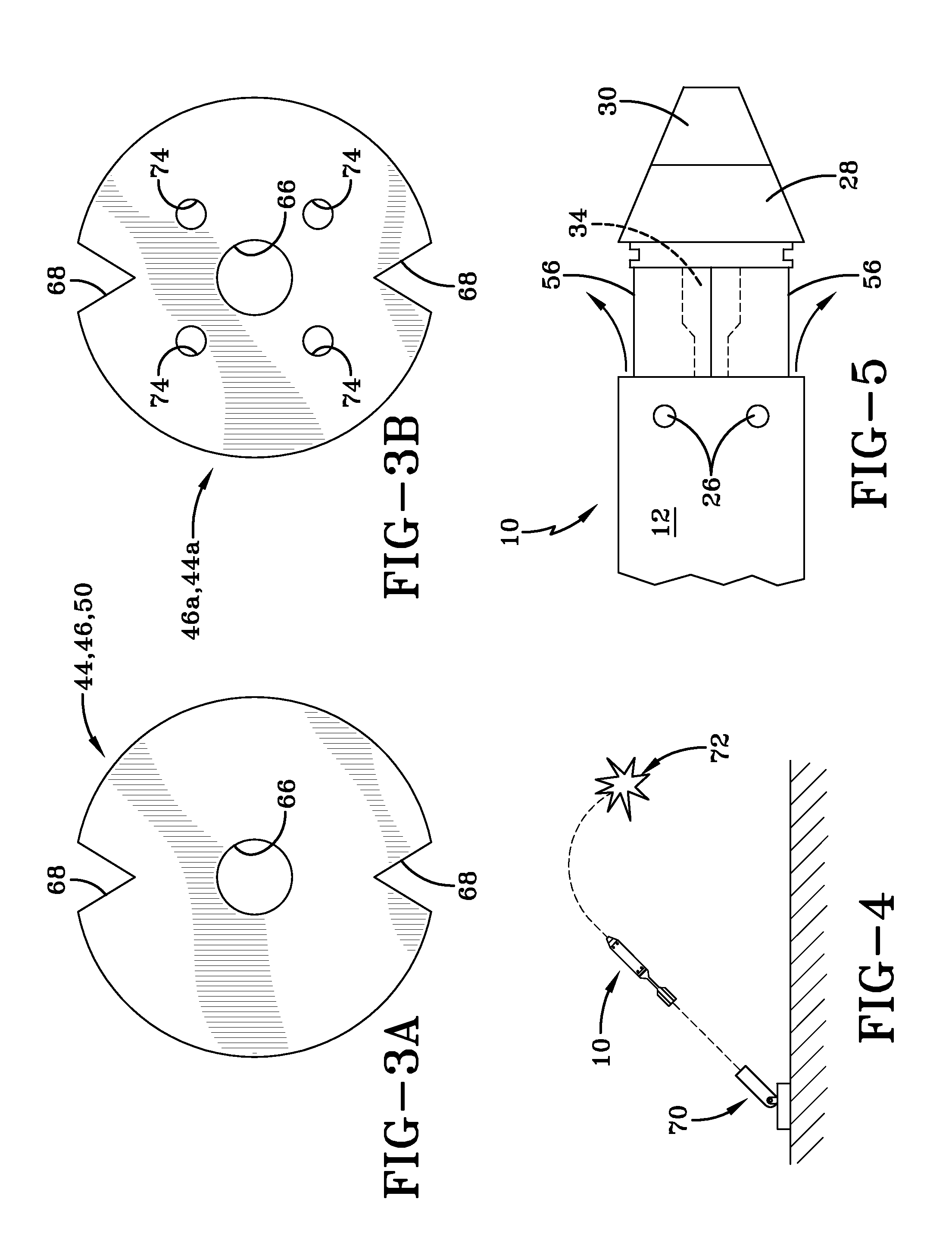
[0022]The invention uses a decelerator in the form of a dual parachute system to maximize the payload volume and bring the body components to the ground at a predetermined terminal velocity while improving reliability and safety. Other properly size decelerators may be used. Unlike a conventional projectile, all components and payloads are ejected through the front of the projectile. The tethering connections between the decelerator and the projectile can be of any type properly selected to withstand the loads of the overall system.

[0023]The deployment sequence starts with launch, then flight, then fuze detonation in air at a preset time at a predetermined height and location. Then, the payload is ejected and the projectile body descends to the ground. The decelerator is attached to the projectile and will bring the body to the ground at a predetermined descent rate. The descent rate is determined by the size and type of decelerator and can be tailored for any application requiremen...


PUM


Abstract

A non-lethal cargo projectile comprises a projectile body; a fuze adapter attached to a front of the projectile body; a fuze attached to the fuze adapter; a boattail attached to a rear of the projectile body; a pressure tube extending from the fuze adapter to the boattail; a decelerator and drogue chute disposed aft of the fuze adapter; a flexible line that connects the pressure tube to the decelerator; a center disc disposed aft of the decelerator and drogue chute; a rear disc disposed aft of the center disc, the center disc and the rear disc defining a payload volume therebetween; a second flexible line that connects the rear disc to the boattail; at least one shearable fastener that fastens the projectile body to the fuze adapter; and at least one vent extending from the boattail to the fuze adapter.

Description

CROSS-REFERENCE TO RELATED APPLICATIONS[0001]This application claims the benefit under 35 USC 119(e) of U.S. provisional patent application 60 / 594,479 filed on Apr. 12, 2005, which is incorporated by reference.STATEMENT OF GOVERNMENT INTEREST[0002]The inventions described herein may be manufactured, used and licensed by or for the U.S. Government for U.S. Government purposes.BACKGROUND OF THE INVENTION[0003]The invention relates in general to munitions and in particular to cargo projectiles that dispense a payload and descend to the ground at a predetermined velocity, which velocity is scaleable for various non-lethal cargo applications.[0004]The specific problem solved by the invention is controlling the descent rate of a projectile that is used for delivering various non-lethal payloads. Non-lethal projectiles should be non-lethal in every aspect. However, conventional non-lethal applications deliver non-lethal payloads using regular projectile cargo shells that descend at high sp...

Claims


Application Information

Patent Timeline
Patent Type & Authority Patents(United States)
IPC IPC(8): F42B12/36
CPCF42B10/56F42B12/60
Inventor HAN, SEUNGEUKTROHANOWSKY, RAYMONDPONIKOWSKI, ANDEW
Owner UNITED STATES OF AMERICA THE AS REPRESENTED BY THE SEC OF THE ARMY
Why Eureka
Try Eureka