Self powered railway monitoring system

a railway monitoring and self-powered technology, applied in the direction of point operation from vehicles, machines/engines, transportation and packaging, etc., can solve the problems of relying on train-based communications to report outdated data regarding operating and traffic conditions, and traditional data gathering systems and methods that do not facilitate real-time data gathering, etc., to facilitate the development of real-time data.

Active Publication Date: 2008-04-29
GENERAL ELECTRIC CO
View PDF18 Cites 11 Cited by
  • Summary
  • Abstract
  • Description
  • Claims
  • Application Information

AI Technical Summary

Benefits of technology

[0006]In accordance with one exemplary embodiment of the present technique, a data gathering apparatus that includes a power generation device configured to generate power in response to traffic on the rail is provided. The data gathering apparatus also includes a sensing device configured to receive power from the power generation device and to sense a property of the traffic traveling on the rail. Advantageously, the data gathering device facilitates the development of real-time data regarding rail conditions and traffic conditions of a railroad network. By way of example, the sensing device, when activated by the operating power from the power generation device, can sense and transmit information regarding the velocity, weight, and any number of other properties of the traffic on the rail.

Problems solved by technology

Unfortunately, traditional data gathering systems and methods do not facilitate the gathering of real-time data related to the railroad assets and traffic conditions during transit between these manned junctions.
For example, traditional techniques that rely on train-based communications are susceptible to human error and, often, report outdated data regarding operating and traffic conditions.
Additionally, traditional remote data gathering devices require a reliable source of operating power, such as an external power grid, which can be relatively expensive to provide in remote and unpopulated areas.
Thus, sensing devices are generally located close to established power grids, leaving vast areas of track unmonitored.
A damaged vehicle, therefore, may cause relatively extensive damage to a rail before the damage is even detected.
For instance, a flat-wheel condition on a vehicle may damage a track over hundreds a miles before it is detected, leading to maintenance costs and downtimes.

Method used


Image

  • Self powered railway monitoring system
  • Self powered railway monitoring system
  • Self powered railway monitoring system

Examples


Embodiment Construction

[0014]As a preliminary matter, the definition of the term “or” for the purpose of the following discussion and the appended claims is intended to be an inclusive “or.” That is, the term “or” is not intended to differentiate between two mutually exclusive alternatives. Rather, the term “or” when employed as a conjunction between two elements is defined as including one element by itself, the other element itself, and combinations and permutations of the elements. For example, a discussion or recitation employing the terminology “A” or “B” includes: “A” by itself, “B” by itself, and any combination thereof, such as “AB” and “BA.” Furthermore, it is of note that the present discussion relates to exemplary embodiments, and the appended claims should not be limited to the embodiments discussed.

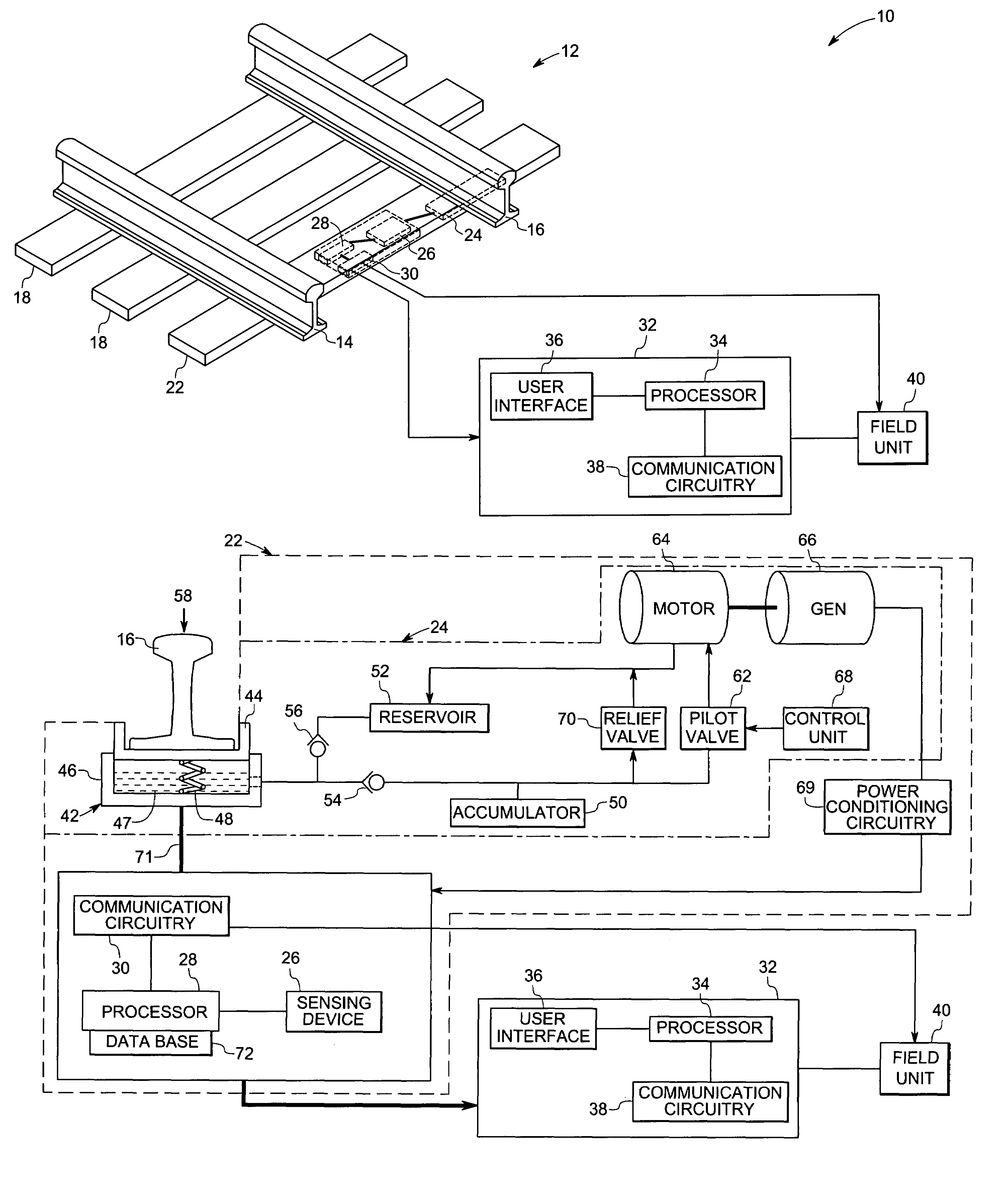
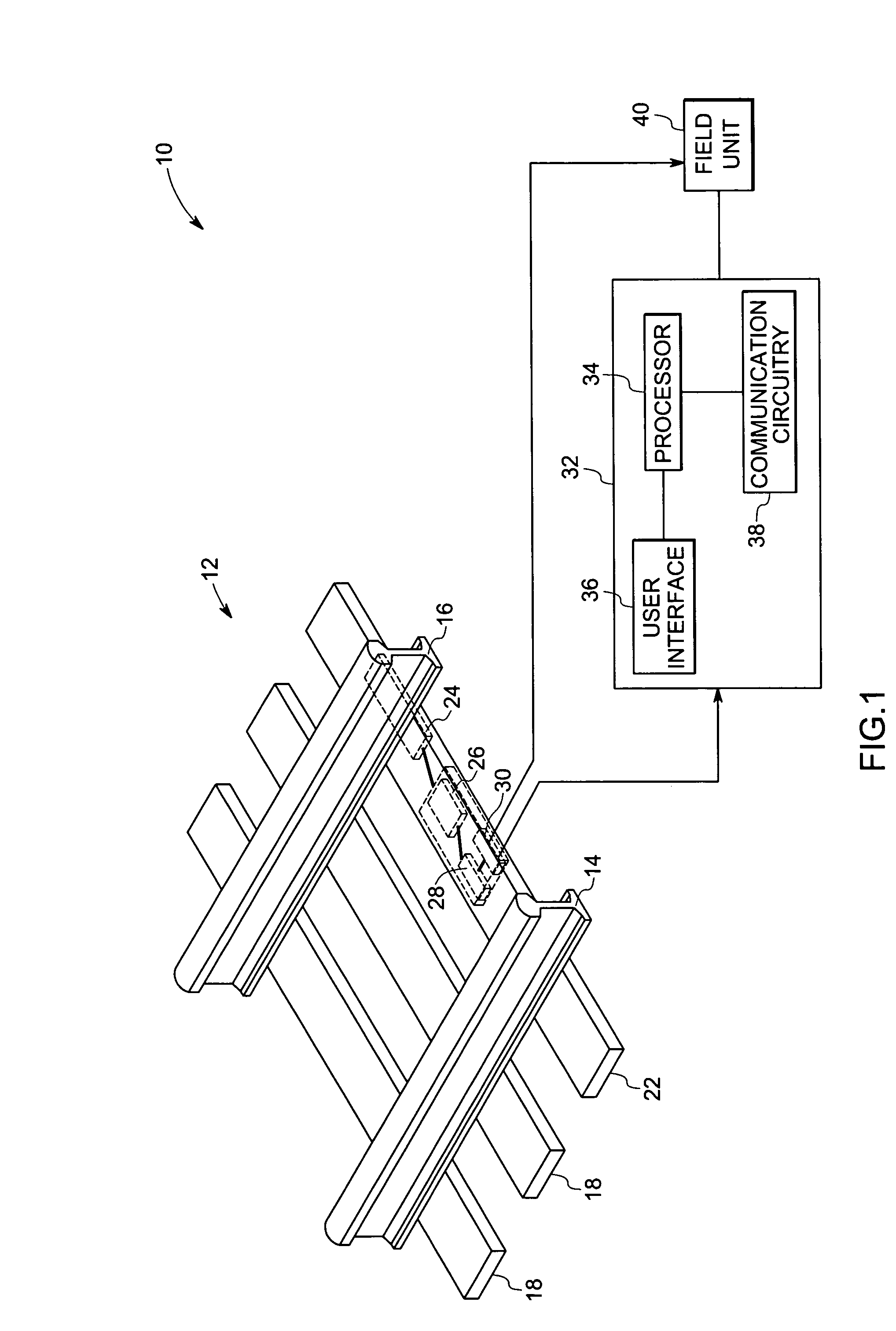
[0015]FIG. 1 illustrates an exemplary railway monitoring system 10. In the illustrated embodiment, the railway monitoring system 10 includes a railway track 12 that has a left rail 14, a right rail...


PUM


Abstract

A data gathering apparatus comprises a power generation device configured to generate power via movement of the rail. The data gathering apparatus further comprises a sensing device configured to receive power from the power generation device and to sense at least one property of the rail, wherein the property of the rail is at least partially defined by a vehicle traveling on the rail.

Description

BACKGROUND[0001]The present invention relates generally to railway monitoring systems and, more specifically, to systems and methods for detecting and / or monitoring various parameters related to rail operations.[0002]Traditionally, data related to railroad traffic and railroad assets is gathered at manned junctions, such as rail yards. By way of example, rail yard workers often manually inspect railcars for damage to determine loading conditions. For instance, railcars are inspected to ensure compliance with the railroad's rules and regulations. As yet another example, rail yard workers often inspect and inventory the incoming and outgoing railcars to manage and facilitate the flow of traffic on a railroad network.[0003]Additionally, some traditional railroad networks employ remote data gathering devices to obtain data regarding traffic between junction areas. For example, traditional remote data gathering methods and devices often employ train-based communications (e.g., radio comm...

Claims


Application Information

Patent Timeline
Patent Type & Authority Patents(United States)
IPC IPC(8): B61L11/00
CPCB61L23/00F03B13/00H10N30/30
Inventor WELLES, II, KENNETH BRAKELEYHERSHEY, JOHN ERIK
Owner GENERAL ELECTRIC CO
Why Eureka
Try Eureka