
Adjustable spinal tether

a spinal tether and adjustable technology, applied in the field of adjustable spinal tethers, can solve the problems of longer operating times

Inactive Publication Date: 2008-05-06
WARSAW ORTHOPEDIC INC
View PDF72 Cites 173 Cited by
  • Summary
  • Abstract
  • Description
  • Claims
  • Application Information

AI Technical Summary

Benefits of technology

The patent describes different apparatus for securely attaching a tether or strand to a grommet or other object. The apparatus includes a polymer strand with a first end and a second end, a first end portion, and a second end portion between the first end and the second end. The polymer strand has an intermediate portion between the end portions. The first end is secured in wrapped condition to form an eyelet in the first end portion. The eyelet has a first side and a second side with an aperture defined between the first side and the second side. The apparatus also includes a crimp with a bore defined therethrough, the second end portion passes through the aperture in a direction from one of the sides to the other of the sides to form a loop. The crimp has a first state and a second state, the first state permitting the polymer strand to move within the bore, the second state locking a portion of the polymer strand within the bore. The apparatus can be used to securely attach a tether or strand to a grommet or other object.

Problems solved by technology

Such precise measurement is difficult prior to surgery and, when done during surgery, results in longer operating times as measurements are taken and a spinal tether of the appropriate length is manufactured.

Method used


Image

  • Adjustable spinal tether
  • Adjustable spinal tether
  • Adjustable spinal tether

Examples


Embodiment Construction

[0050]For the purposes of promoting an understanding of the principles of the invention, reference will now be made to the embodiments illustrated in the drawings and specific language will be used to describe the same. It will nevertheless be understood that no limitation of the scope of the invention is thereby intended, such alterations and further modifications in the illustrated devices, and such further applications of the principles of the invention as illustrated therein being contemplated as would normally occur to one skilled in the art to which the invention relates.

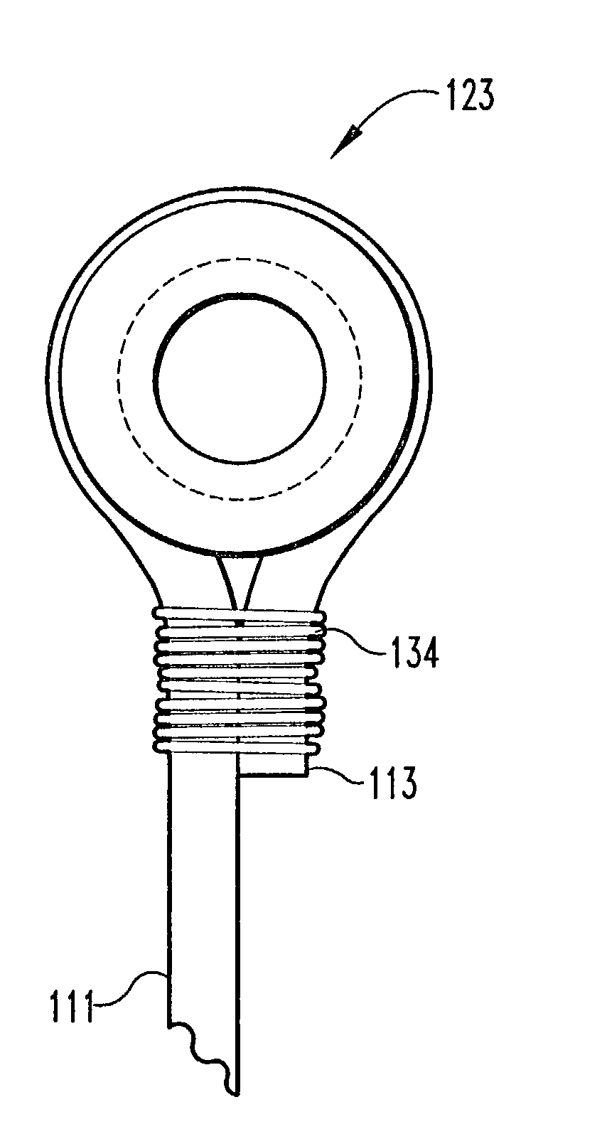
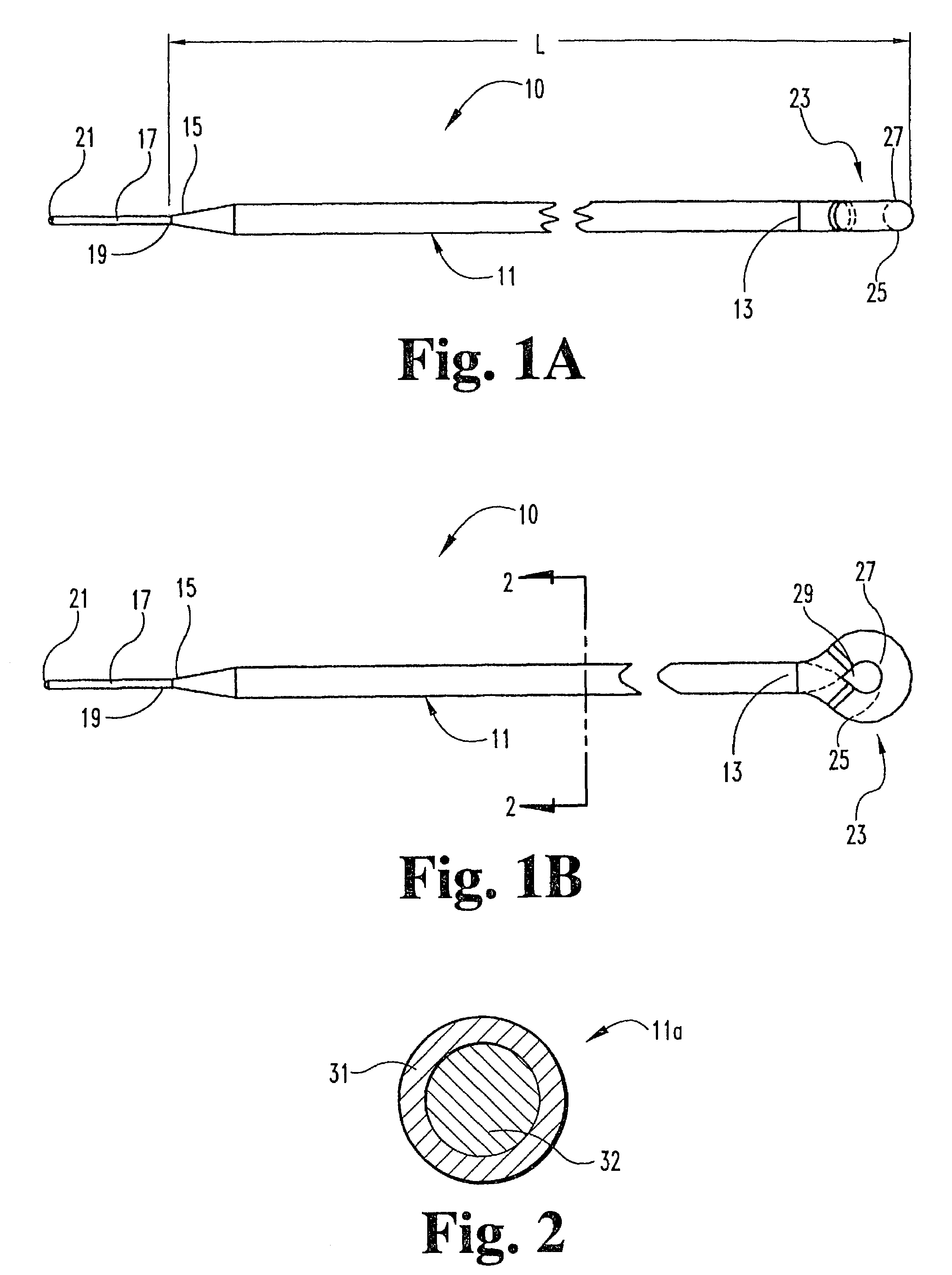
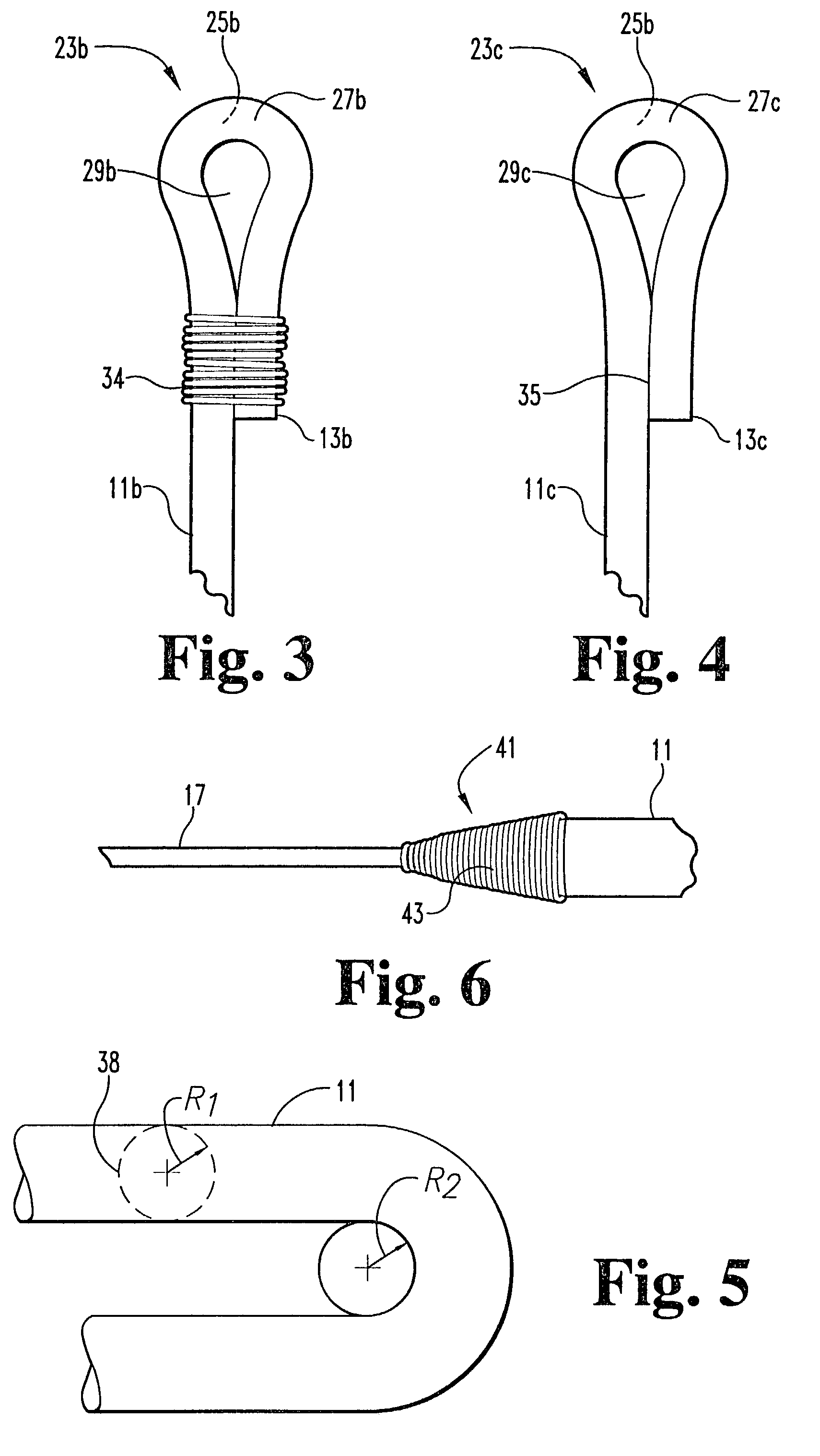
[0051]With reference to FIGS. 1A and 1B, an adjustable spinal tether 10 comprises a leader 17 attached to an artificial strand 11. Artificial strand 11 has a first end 13 and a second end 15. The total length L of strand portion of the tether is preferably about one meter. This length may be varied as desired. Leader 17 has a first end 19 which is attached to the second end 15 of artificial strand 11. The seco...


PUM


Abstract

An improved apparatus is provided to allow for an adjustable length tether for use in the spine and other parts of the body. The tether comprises an artificial strand with an eyelet formed in one end, the other end being looped through the eyelet. The other end is then secured with respect to the eyelet by a crimp, the excess length being cut off after the length of the tether has been given an appropriate tension. Alternatively, the eyelet end may be formed around a grommet. The crimp may be separate from the grommet or a part of the grommet. The mechanism by which the length is adjusted in some cases will take advantage of the shape memory properties of alloys such as nickel-titanium.

Description

CROSS REFERENCE TO RELATED APPLICATIONS[0001]The present application is a continuation of U.S. patent application Ser. No. 09 / 421,976, filed on Oct. 20, 1999, now U.S. Pat. No. 6,436,099 B1, which claims the benefit of Provisional Application Ser. No. 60 / 130,910, filed on Apr. 23, 1999, the contents of each application hereby being incorporated by reference.BACKGROUND OF THE INVENTION[0002]Various types of spinal column disorders are known and include scoliosis (abnormal curvature of the spine), kyphosis (backward curvature of the spine), spondylolisthesis (forward displacement of a lumbar vertebra), and other disorders such as ruptured or slipped discs, broken or fractured vertebrae, and the like. Procedures to stabilize areas of the spine for both fusing spinal vertebrae together and for other stabilization purposes often require the use of a spinal tether. The existing spinal tethers, of which we are aware on the market, come in straight lengths or circular, “loop” geometries. Th...

Claims


Application Information

Patent Timeline
Patent Type & Authority Patents(United States)
IPC IPC(8): A61B17/56A61B17/00A61B17/70A61B17/82A61F2/48
CPCA61B17/7022A61B17/82A61B2017/00858
Inventor DREWRY, TROY D.SHERMAN, MICHAEL C.BRUMFIELD, DAVID L.
Owner WARSAW ORTHOPEDIC INC
Learn More