Shared phased array beamformer

a beamformer and phased array technology, applied in the direction of antennas, electrical equipment, radio transmission, etc., can solve the problems of waste of beams assigned to one or more phased array apertures, inability to provide effective coverage,

Active Publication Date: 2008-05-06
LOCKHEED MARTIN CORP
View PDF29 Cites 236 Cited by
  • Summary
  • Abstract
  • Description
  • Claims
  • Application Information

AI Technical Summary

Problems solved by technology

However, during particular times and at particular locations in the satellite's orbit, one or more of the apertures may be positioned in such an orientation as to not provide useful coverage.
Due to these different electromagnetic operating characteristics, useful coverage may also not be provided at all times. Due to these periods of poor coverage, the beams assigned to one or more of the phased array apertures are wasted since they can not establish communication links.

Method used


Image

  • Shared phased array beamformer
  • Shared phased array beamformer
  • Shared phased array beamformer

Examples


Embodiment Construction

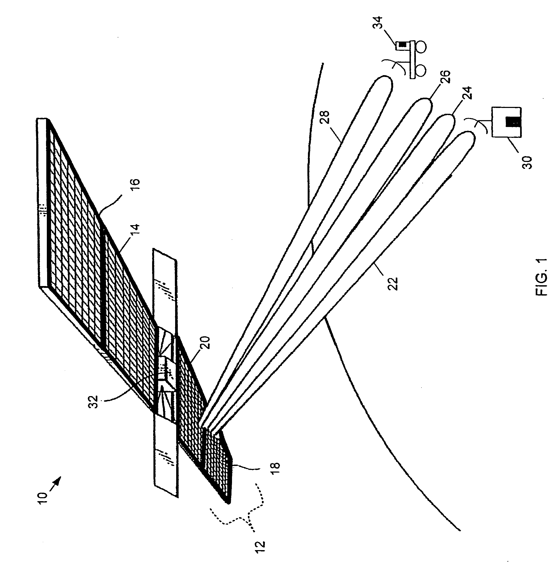
[0019]Referring to FIG. 1, a satellite 10 is shown in orbit and includes a phased array antenna system 12 that is capable of producing multiple beams. Phased array antenna system 12 includes four apertures 14, 16, 18 and 20. In this representation, apertures 14 and 16 are shown producing four distinct beams 22, 24, 26, and 28. Each of these beams may be used for transmitting and / or receiving electromagnetic signals to and from locations respectively covered by phased array antenna system 12. For example, beam 22 may be used to receive an electromagnetic signal (e.g., a radio frequency (RF) signal, etc.) that is transmitted from a ground station 30 that is covered by beam 22. To receive the electromagnetic signal on beam 22, phased array antenna system 12 or a portion of the phased array antenna system (e.g., aperture 18) is designed to operate at one or more frequencies (e.g., C-band, Ku-band, etc.) within the electromagnetic spectrum in which ground station 30 transmits. Additional...


PUM


Abstract

A shared beamformer flexibly allocates beams among phased array antenna apertures of a satellite (or other type of platform). By sharing the beamformer among the apertures, if one aperture is not providing useful coverage (due to orientation, traffic volume, signal frequency, signal polarization, etc.), the beams may be reallocated to one or more other apertures that are providing useful coverage. To share the beamformer among the phased array antenna apertures, a selector network (e.g., one or more switches) is used to select which particular apertures are to send or receive signals.

Description

CROSS-REFERENCE TO RELATED APPLICATION[0001]This is a divisional application of U.S. patent application Ser. No. 11 / 117,381, filed Apr. 29, 2005, now U.S. Pat. No. 7,180,447 which is hereby incorporated herein by reference in its entirety for all purposes.TECHNICAL FIELD[0002]This disclosure relates to phased array antenna systems and, more particularly, to beamformers for phased array antenna systems.BACKGROUND[0003]With the advances in wireless technology, satellites such as low earth orbit satellites are used in telecommunication systems to establish communication links across large distances. To produce these links, phased array antennas have been incorporated into some satellites as well as mobile and stationary ground stations. A phased array antenna has an aperture that is assembled from a large number of radiating elements, such as slots or dipoles. By individually controlling a phase shift and attenuation that is applied to each element, predictable beams may be formed and ...

Claims


Application Information

Patent Timeline
Patent Type & Authority Patents(United States)
IPC IPC(8): H01Q3/24
CPCH01Q3/24H01Q3/36H01Q3/40H04B7/18515
Inventor JACOMB-HOOD, ANTHONY W.
Owner LOCKHEED MARTIN CORP
Why Eureka
Try Eureka