Packer element retaining system

a packer element and retaining system technology, applied in the direction of sealing/packing, cable termination, borehole/well accessories, etc., can solve the problems of unusable extrusion of packer elements, complicated and expensive problems

Active Publication Date: 2008-05-20
HALLIBURTON ENERGY SERVICES INC
View PDF47 Cites 109 Cited by
  • Summary
  • Abstract
  • Description
  • Claims
  • Application Information

AI Technical Summary

Problems solved by technology

The shoes are typically segmented and, when the tool is set in a well, spaces between the expanded segments have been found to allow undesirable extrusion of the packer elements, at least in high pressure and high temperature wells.
Numerous improvements have been made in efforts to prevent the extrusion of the packer elements, and while some have been effective to some extent, they have been complicated and expensive.

Method used


Image

  • Packer element retaining system
  • Packer element retaining system
  • Packer element retaining system

Examples


Embodiment Construction

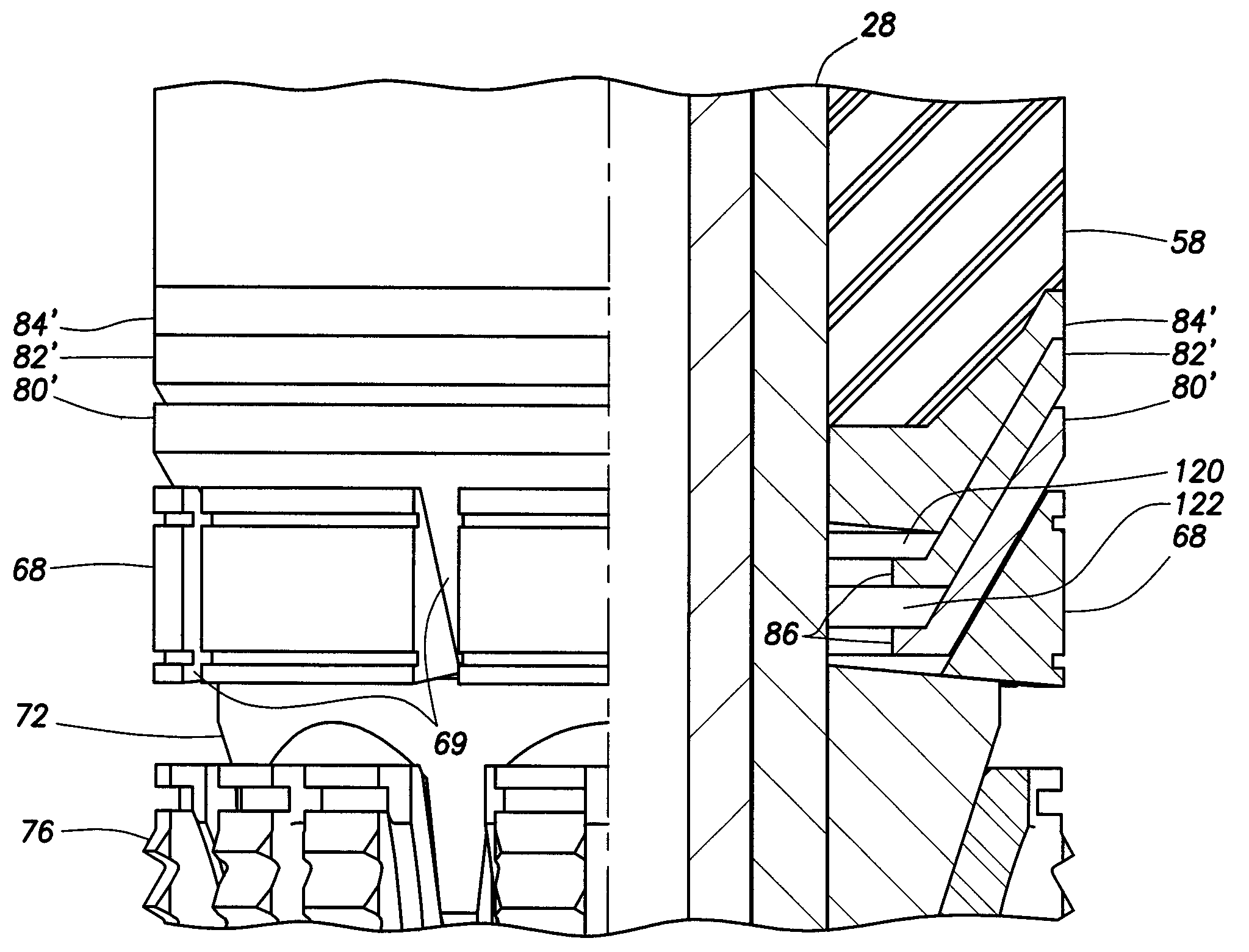
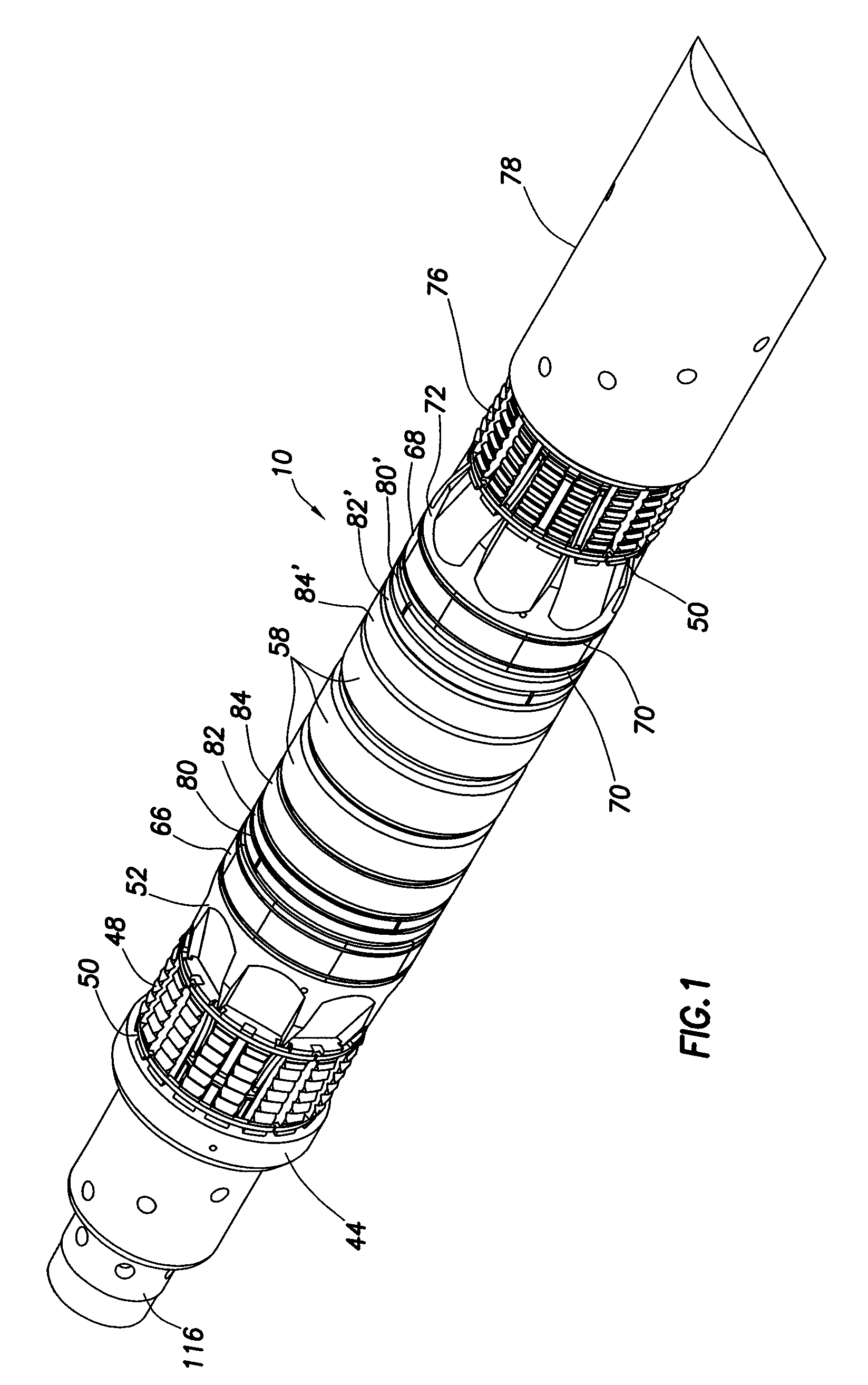
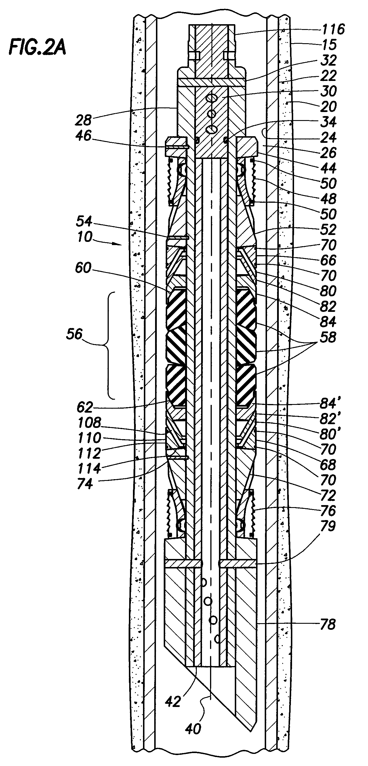
[0020]FIG. 1 is a perspective view of a bridge plug embodiment 10 in an unset or run in condition. In FIGS. 2A and 2B, the bridge plug 10 is shown in the unset condition in a well 15. The well 15 may be either a cased completion with a casing 22 cemented therein by cement 20 as shown in FIG. 2A or an openhole completion. Bridge plug 10 is shown in set position in FIGS. 3A and 3B. Casing 22 has an inner surface 24. An annulus 26 is defined between casing 22 and downhole tool 10. Downhole tool 10 has a packer mandrel 28, and is referred to as a bridge plug due to a plug 30 being pinned within packer mandrel 28 by radially oriented pins 32. Plug 30 has a seal means 34 located between plug 30 and the internal diameter of packer mandrel 28 to prevent fluid flow therebetween. The overall downhole tool 10 structure, however, is adaptable to tools referred to as packers, which typically have at least one means for allowing fluid communication through the tool. Packers may therefore allow fo...


PUM


Abstract

A bridge plug having a segmented backup shoe, and at least one split cone extrusion limiter, the extrusion limiter comprising a two part conical retainer positioned between packer elements and the segmented backup shoe to block packer element extrusion though spaces between backup shoe segments. In one embodiment, two split cone extrusion limiters are used together and positioned so that each split cone extrusion limiter covers gaps in the other extrusion limiter and together the two split cone extrusion limiters block packer element extrusion though gaps between backup shoe segments regardless of their orientation relative to the segmented backup shoe. In one embodiment, a solid retaining ring is positioned between a split retaining cone extrusion limiter and a packer element and resists extrusion of packer elements into spaces in the split cone extrusion limiter or limiters.

Description

CROSS-REFERENCE TO RELATED APPLICATIONS[0001]None.STATEMENT REGARDING FEDERALLY SPONSORED RESEARCH OR DEVELOPMENT[0002]Not applicable.REFERENCE TO A MICROFICHE APPENDIX[0003]Not applicable.FIELD OF THE INVENTION[0004]This invention relates to packer and bridge plug type tools used in wellbores and more particularly to a retainer system which resists extrusion of packer elements when exposed to borehole conditions, especially high pressure and high temperature.BACKGROUND OF THE INVENTION[0005]In the drilling or reworking of oil wells, a great variety of downhole tools are used. For example, but not by way of limitation, it is often desirable to seal tubing or other pipe in the casing of the well, such as when it is desired to pump cement or other slurry down the tubing and force the cement or slurry around the annulus of the tubing or out into a formation. It then becomes necessary to seal the tubing with respect to the well casing and to prevent the fluid pressure of the slurry from...

Claims


Application Information

Patent Timeline
Patent Type & Authority Patents(United States)
IPC IPC(8): E21B33/12
CPCE21B33/1216
Inventor SMITH, DONALDWINSLOW, DONNYSUTTON, MIKEMARTIN, TRACY
Owner HALLIBURTON ENERGY SERVICES INC
Why Eureka
Try Eureka