Connector

a technology of connecting rods and connectors, applied in the direction of coupling contact members, coupling device connections, securing/insulating coupling contact members, etc., can solve the problems of reducing the contact force of the male tab. , to achieve the effect of improving contact reliability, preventing interference, and strengthening the contact pressur

Inactive Publication Date: 2008-05-20
SUMITOMO WIRING SYST LTD +1
View PDF16 Cites 21 Cited by
  • Summary
  • Abstract
  • Description
  • Claims
  • Application Information

AI Technical Summary

Benefits of technology

[0008]The extending end of the tongue preferably is supported in contact with at least one support at least when the male tab and the contact point are connected. The support is raised from the bottom wall and prevents interference between the locking projection and the tongue. Further, the tongue preferably is supported at the front edge and at the extending end. Therefore, a contact pressure with the male tab can be strengthened to improve contact reliability, as compared to a case where the tongue is supported only at one point.
[0009]The support preferably is formed by bending in an area of the main portion from the bottom wall to a side wall. Accordingly, the supporting surface can be provided easily and inexpensively.
[0010]Two supports preferably are provided and are spaced apart in the width direction. Thus, the tongue can be supported in a stable posture without being twisted.
[0011]The support preferably is a cantilever formed by bending a wall of the main portion in, and an opening left in the bottom wall by the bending preferably communicates with the locking hole. Accordingly, the support can be provided easily and inexpensively.
[0016]At least one projection preferably bulges out from at least one widthwise lateral edge of the tongue. At least one preventing portion is formed at a side wall of the main portion facing the projection. The projection engages the preventing portion to prevent an excessive deformation of the tongue when the tongue is deformed within the resiliency limit thereof.

Problems solved by technology

As a result, a dimension of the locking hole in forward and backward directions is restricted.
Furthermore, a shear area of the locking projection is restricted.
Thus, the lock may not exert a sufficient holding force to resist a rearward pulling force on the terminal fitting.

Method used


Image

  • Connector
  • Connector
  • Connector

Examples


first embodiment

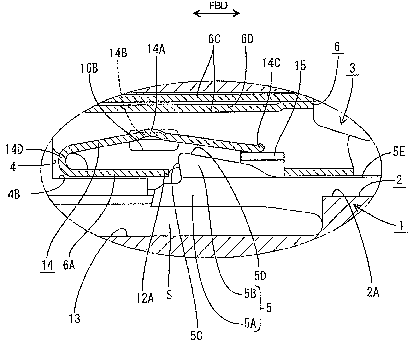
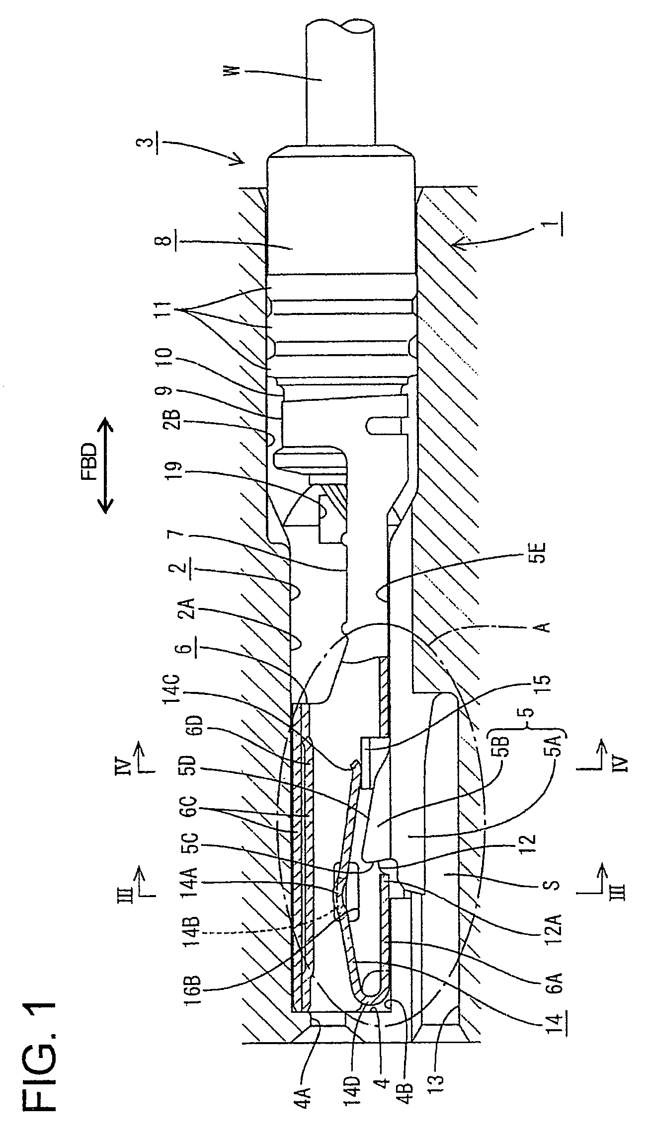
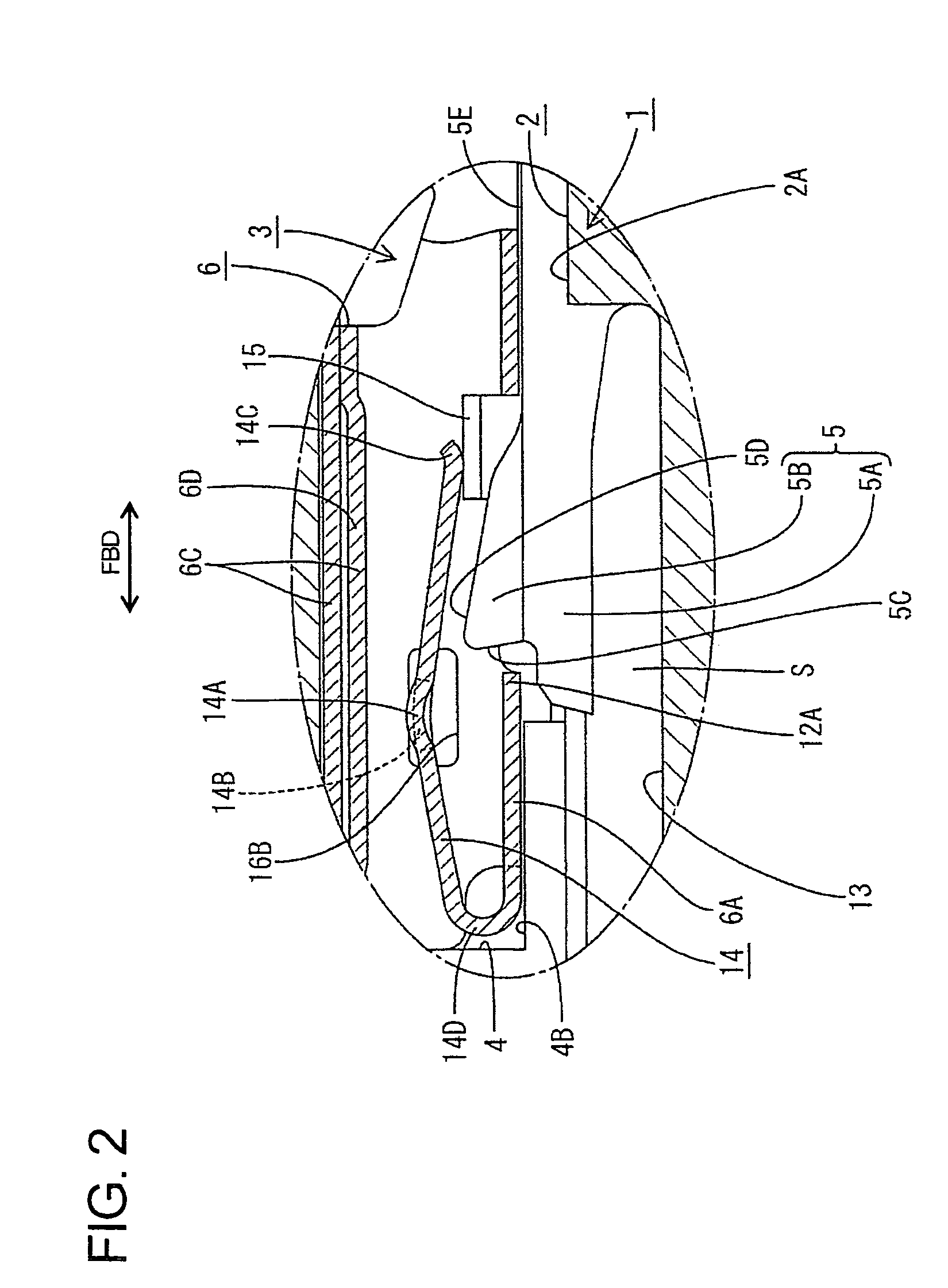
[0035]A connector according to the invention is described with reference to FIGS. 1 to 12. The connector includes a housing 1 with opposite front and rear ends that are spaced apart in forward and backward directions FBD. The front end of the housing 1 is the end that is to be connected with a mating connector. A cavity 2 penetrates through the housing 1 substantially in the forward and backward directions FBD. A terminal accommodating hole 2A is defined at a front portion of the cavity 2 and has a substantially rectangular cross section. A plug mounting hole 2B is defined at a rear portion of the cavity 2 and has a substantially round cross section. A terminal fitting 3 can be accommodated into the cavity 2 from behind as shown in FIG. 1. The terminal fitting 3 is stopped at its front position by a front wall 4 of the cavity 2, and is prevented from coming out backward by a lock 5 in the cavity 2. Further, a male-tab insertion hole 4A is formed in the front wall 4 for receiving a m...

third embodiment

[0053]the invention is described with reference to FIGS. 15 to 17. The connector of this embodiment has a terminal fitting 3 with supports 15 that differ from the supports of the first embodiment. Other parts of the connector, however, are substantially the same, and are not described. Specifically, the supports 15 of the first embodiment are formed by bending lower parts of the side walls 6B inward. However, a support 21 of this embodiment is formed by forming two slits extending back from the opposite widthwise edges of the locking hole 12 and bending a portion between the slits inward of the main portion 6. An opening left in the bottom wall 6A by the above bending forms part of the locking hole 12. The bent portion has a slanted panel sloped up towards the front from the bottom wall 6A and the support 21 extends substantially horizontally forward from the front edge of the slanted panel. Two supporting projections 22 bulge out from the opposite widthwise edges of the support 21,...


PUM


Abstract

A connector has a housing (1) with a cavity (2) for receiving a terminal fitting (3). The terminal fitting (3) has a tubular main portion (6) and a locking hole (12) is formed in the main portion (6) for receiving locking projection (5B) of a lock (5). A tongue (14) extends from the front end of the main portion (6) and is folded back into the main portion (6). The front end of the locking projection (5B) is located before an extending end (14C) of the tongue (14) and the rear end thereof is located behind the extending end (14C) of the tongue (14). Accordingly, the locking projection (5B) is long at a position where a front end surface (5C) of the locking projection (5B) receives a shear force from a front edge (12A) of the locking hole (12), thereby enlarging a sectional area against the shear force.

Description

BACKGROUND OF THE INVENTION[0001]1. Field of the Invention[0002]The invention relates to a connector.[0003]2. Description of the Related Art[0004]Japanese Unexamined Patent Publication No. 2000-357555 discloses a connector with a housing having a cavity that penetrates the housing in forward and backward directions. The connector also includes a terminal fitting that can be inserted into the cavity. The terminal fitting has a tubular main portion with a bottom wall and a locking hole is formed in the bottom wall. A tongue extends from the front edge of the bottom wall and is folded back into the main portion. An extending end of the tongue is supported on the inner surface of the bottom wall behind the locking hole. Thus, the tongue is supported at two points. A lock projects into the cavity and has a locking projection. The locking projection enters the main portion and engages the front edge of the locking hole to prevent the terminal fitting from coming out backward from the cavi...

Claims


Application Information

Patent Timeline
Patent Type & Authority Patents(United States)
IPC IPC(8): H01R13/11
CPCH01R13/113H01R13/5205
Inventor TANAKA, TSUTOMU
Owner SUMITOMO WIRING SYST LTD
Why Eureka
Try Eureka