
Data communications system and method for communication between infrared devices

a data communication and infrared technology, applied in the field of data communication between infrared (ir) devices, can solve the problems of imposing communication constraints, requiring extensive manual servicing and maintenance of devices such as ir controlled faucets, and a myriad of operating pitfalls. achieve the effect of facilitating communication

Active Publication Date: 2008-05-20
GEBERIT INT AG
View PDF46 Cites 4 Cited by
  • Summary
  • Abstract
  • Description
  • Claims
  • Application Information

AI Technical Summary

Problems solved by technology

In particular, the IrDA Physical Layer Specification places constraints on the communication procedure when a device attempts to establish an optical link with a second device.
Automatically activated fluid dispensing devices have a myriad of operating pitfalls.
For example, devices such as IR controlled faucets require extensive manual servicing and maintenance.
Inherently, in an environment such as an office building having numerous floors and numerous faucets in each of the restrooms on each of the floors, servicing and maintenance of the IR controlled devices is often a burdensome and time consuming task.

Method used


Image

  • Data communications system and method for communication between infrared devices
  • Data communications system and method for communication between infrared devices
  • Data communications system and method for communication between infrared devices

Examples


Embodiment Construction

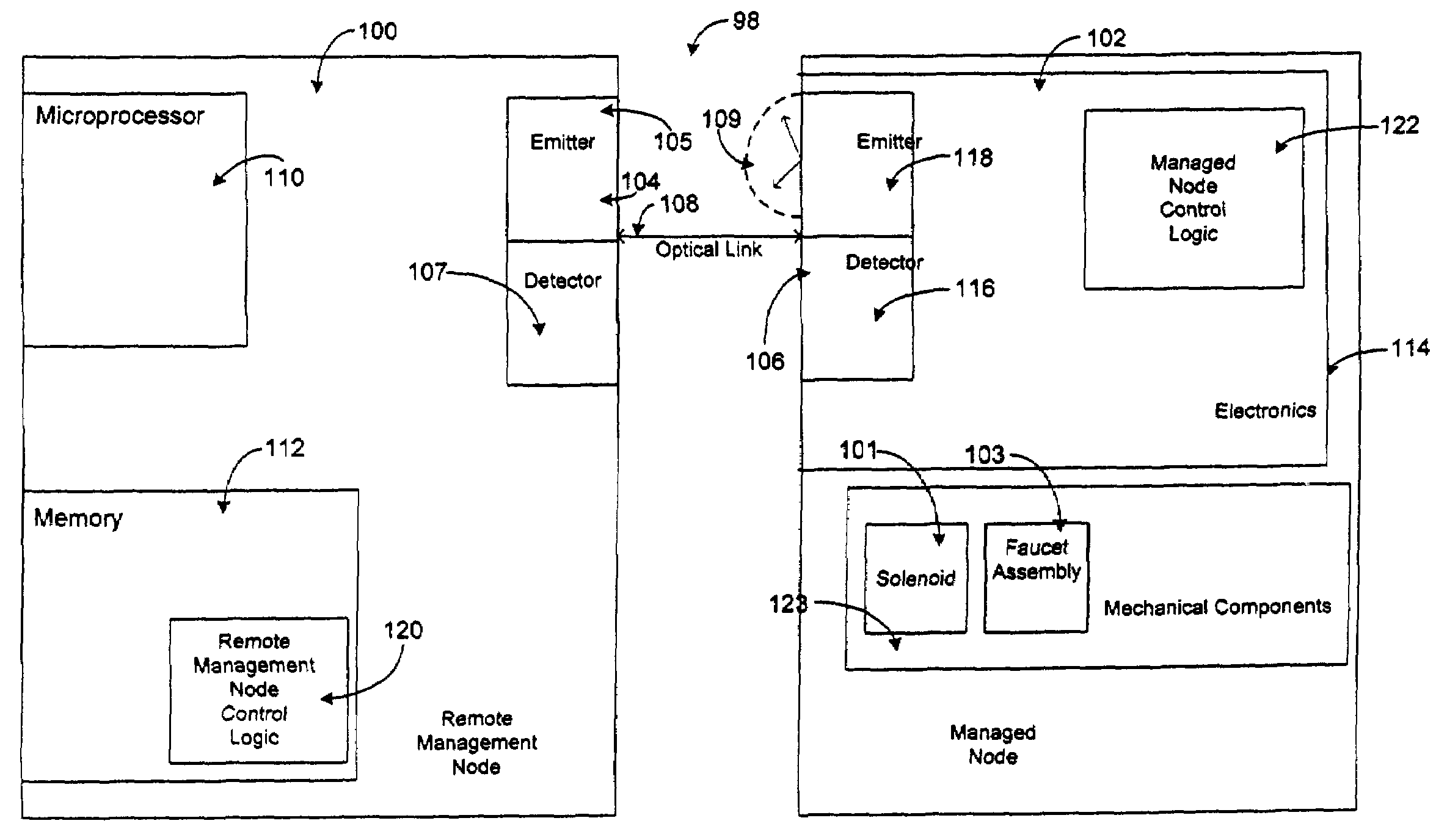
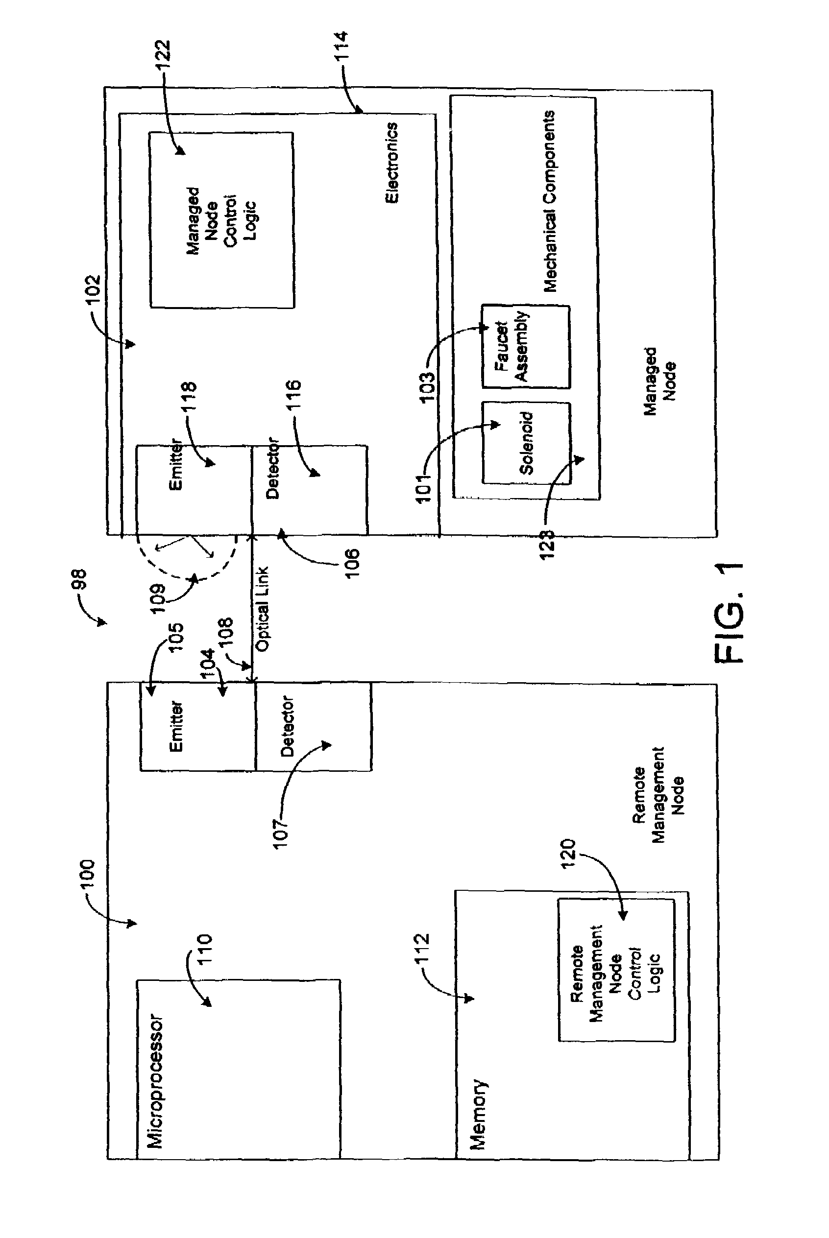
[0038]Reference is now made in detail to a present preferred embodiment of the present invention, examples of which are illustrated in the accompanying drawings. Wherever possible, the same reference numerals will be used throughout the drawing figures to refer to the same or like parts. An exemplary embodiment of the data communication system and method of the present invention is illustrated in the block diagram of FIG. 1 and is designated generally throughout by reference numeral 98.

[0039]In accordance with the invention, the hardware elements of the data communication system of the present invention include Remote Management Node 100 and Managed Node 102. Remote Management Node 100 includes generally an optical interface port 104, a processing element 110, and a memory element 112. Managed Node 102 includes generally an optical interface port 106 and an electronics module 114. The optical interface port 106 of Managed Node 102 includes an emitter 118 and a detector 116. The emit...


PUM


Abstract

A data communication system for facilitating communication between infrared devices having an initiating optical interface port that includes an IR emitter and an optical sensor. A receiving optical interface port includes an active IR emitter that emits a pulse at a predetermined interval and an optical sensor. A software application causes an Attention Signal to be emitted from the initiating IR emitter where the initiating IR emitter is positioned in detection range of the receiving optical sensor. The receiving optical interface port is controlled by a firmware application. The firmware is designed to discontinue the pulse of the active IR emitter upon detection of the Attention Signal. Once the normal pulse cycle is discontinued, the active IR emitter is then employed for transmitting data signals to the initiating optical interface port, thereby establishing an optical link between the initiating optical interface port and the receiving optical interface port. The normal operations of the IR emitter of the receiving optical interface port remain discontinued until communication between the ports is terminated, allowing data signals to be sent to the initiating optical sensor from the active IR emitter.

Description

CROSS-REFERENCE TO RELATED APPLICATIONS[0001]This application claims the benefit of U.S. Provisional Patent Application Ser. No. 60 / 267,441 entitled, “Remotely Managed Automatic Dispensing Apparatus and Method”, filed on Feb. 8, 2001, and U.S. Provisional Patent Application Ser. No. 60 / 242,898 entitled, “Remotely Managed Automatic Dispensing Apparatus and Method”, filed on Oct. 24, 2000, both of which are hereby incorporated by reference herein.BACKGROUND OF INVENTION[0002]1. Field of the Invention[0003]The present invention relates generally to the field a data communications between infrared (IR) devices, and more particularly to data communication between a handheld computer having an optical interface port that transmits and receives signals with an optical interface port of an automatically activated fluid dispensing device.[0004]2. Technical Background[0005]Standard IR devices communicate in accordance with the Infrared Data Association Serial Infrared Physical Layer Specifica...

Claims


Application Information

Patent Timeline
Patent Type & Authority Patents(United States)
IPC IPC(8): H04B10/00G07F9/02G07F13/02G08C23/04H04B10/10
CPCG06Q20/327G07F9/02G07F13/025G08C23/04H04B10/114G08C2201/42G08C2201/51G07F9/001
Inventor PATTERSON, WADE C.WATSON, THOMAS J.
Owner GEBERIT INT AG
Learn More