Method and system for automatic gain control of sensors in time-of-flight systems

a technology of automatic gain control and sensor, applied in the field of cmosimplementable image sensors, can solve the problems of difficult computer program to judge object distance, inability to simultaneously measure distance for all objects in the field of view, and inability to achieve accurate depth data, the effect of maximizing the number of pixel detector sensors

Inactive Publication Date: 2008-05-27
MICROSOFT TECH LICENSING LLC
View PDF1 Cites 108 Cited by
  • Summary
  • Abstract
  • Description
  • Claims
  • Application Information

AI Technical Summary

Benefits of technology

[0026]Preferably operable with differential mode sensing, the present invention examines four phases of detected signals, after which the passive brightness mode (e.g., ambient light) amplitude component of the detected signals is examined. If brightness data indicate sensor saturation at present (e.g., ambient optical energy is too high for the pixel photodetectors to detect within their dynamic range), then the present invention commands one or more compensatory parameters in the TOF system, for example varying the number of common mode resets, varying the signal integration time, varying system gain, etc. An object is to maximize the number of pixel photodetectors that are operating within their intended dynamic range, and thus can output accurate depth data. More specifically, in one embodiment a histogram is calculated using active mode brightness mode. Thus, the present invention first compensates the TOF sensors by varying common mode resets to accommodate passive optical energy levels, and then to compensate for active optical energy levels. Embodiments of the present invention can also adjust common mode resets, system parameters including integration time and video gain. These adjustments may be in addition to or in lieu of common mode reset adjustments. Implementation of the present invention maximizes the number of pixel detector sensors in the sensor array that output valid depth measurements.

Problems solved by technology

However brightness or luminosity-based systems may erroneously yield the same measurement information for a distant target object that may be large with a shiny surface and is thus highly reflective, as for a smaller target object that is closer to the system but has a dull surface that is less reflective.
But in general, luminosity-based systems do not work well and are subject to error, as noted above.
At best these prior art focus systems can focus a lens onto a single object in a field of view, but cannot simultaneously measure distance for all objects in the field of view.
However it is challenging for a computer program to judge object distance from a stereoscopic image.
Errors are often present, and the required signal processing requires specialized hardware and computation.
But in practice it is difficult to accurately extract distance and velocity data along a viewing axis from luminosity measurements.
The necessary distance measurements may be erroneous due to varying lighting conditions and other shortcomings noted above.
Understandably having to provide precision moving mechanical parts add bulk, complexity, and cost to such range finding system.
Further, because these systems sample each pixel sequentially, the number of complete image frames that can be sampled per unit time is limited.
Although specialized three dimensional imaging systems exist in the nuclear magnetic resonance and scanning laser tomography fields, such systems require substantial equipment expenditures.
Further, these systems are obtrusive, and are dedicated to specific tasks, e.g., imaging internal body organs.
For example, if a CCD range finder system were used in a digital zoom lens application, even though most of the relevant data would be provided by a few of the CCDs in the array, it would nonetheless be necessary to readout the entire array to gain access to the relevant data, a time consuming process.
While many types of three-dimensional TOF imaging systems are known in the art, obtaining reasonably accurate depth images from such systems can be challenging.
As noted in many of the above-referenced patents, sensor performance may be impaired by many parameters.
Some or all sensors may not receive sufficient optical energy to perform well, in which case a reliable measurement of depth z cannot be obtained.
Similarly, some or all sensors may receive too much optical energy, in which case the sensors may overload and saturate, with the result that a reliable measurement of depth z cannot be obtained.

Method used


Image

  • Method and system for automatic gain control of sensors in time-of-flight systems
  • Method and system for automatic gain control of sensors in time-of-flight systems
  • Method and system for automatic gain control of sensors in time-of-flight systems

Examples


Embodiment Construction

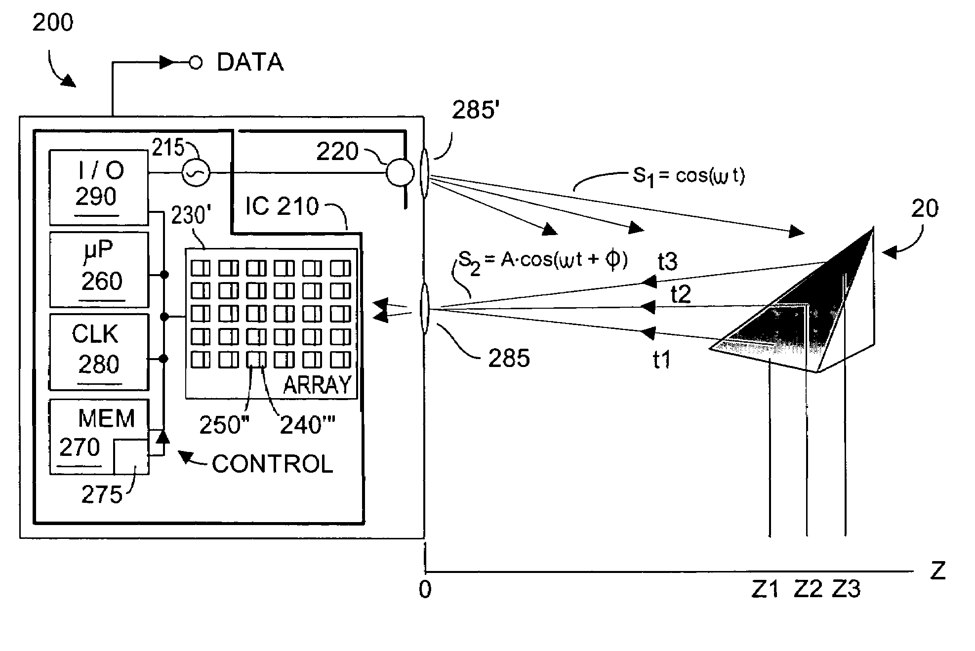
[0036]FIG. 3 depicts a TOF system 200 with which the present invention, denoted 275, may be practiced to improve the validity of z depth measurements output as DATA. Element 275 preferably is software that when executed by microprocessor 260 carries out method steps, exemplified by the pseudocode of FIGS. 4-6. The present invention maximizes the number of photodetector pixels 240′″ in array 230 that operate within their intended dynamic range. The present invention can exercise control (depicted in FIG. 3 as CONTROL) over at least one parameter of TOF system 200. For example, if the present invention determines that too many photodetectors are saturating, a CONTROL signal can be generated varying at least one TOF system 200 parameter. For example, the CONTROL signal may cause TOF system 200 to more frequently reset common mode in the detectors, as described in U.S. Pat. No. 6,919,549 (2005) Method and System to Differentially Enhance Sensor Dynamic Range, and / or to reduce detection ...


PUM


Abstract

Performance of pixel detectors in a TOF imaging system is dynamically adjusted to improve dynamic range to maximize the number of pixel detectors that output valid data. The invention traverses the system-acquired z depth, the brightness, and the active brightness images, and assigns each pixel a quantized value. Quantization values encompass pixels receiving too little light, normal light, to too much light. Pixels are grouped into quantized category groups, whose populations are represented by a histogram. If the number of pixels in the normal category exceeds a threshold, no immediate corrective action is taken. If the number of pixel receiving too little (or too much) light exceeds those receiving too much (or too little) light, the invention commands at least one system parameter change to increase (or decrease) light reaching the pixels. Controllable TOF system parameters can include exposure time, common mode resets, video gain, among others.

Description

CROSS-REFERENCES TO RELATED APPLICATIONS[0001]Priority is claimed from co-pending U.S. provisional patent application No. 60 / 650,916 filed 8 Feb. 2005 entitled “A Method for Automated Gain Control on Time of Flight Sensors”, Salih Burak Gokturk, inventor, Canesta, Inc., assignee.FIELD OF THE INVENTION[0002]The invention relates generally to CMOS-implementable image sensors suitable for time-of-flight three-dimensional applications including range and camera sensors, and more specifically to dynamically varying at least one TOF system parameter to maximize the number of photodetector sensors operating within their intended dynamic range. In this fashion, more reliable depth measurement data is obtained from a greater number of pixel photodiode sensors.BACKGROUND OF THE INVENTION[0003]Electronic camera and range sensor systems that provide a measure of distance z from the system to a target object are known in the art. Many such systems approximate the range to the target object based...

Claims


Application Information

Patent Timeline
Patent Type & Authority Patents(United States)
IPC IPC(8): G01C3/08
CPCG01C3/08
Inventor RAFII, ABBASGOKTURK, SALIH BURAK
Owner MICROSOFT TECH LICENSING LLC
Why Eureka
Try Eureka