Check patentability & draft patents in minutes with Patsnap Eureka AI!

Method and control for determining low refrigerant charge

a low refrigerant charge and charge technology, applied in the direction of instruments, heat measurement, lighting and heating apparatus, etc., can solve the problem of inaccurate mass flow rate calculation

Inactive Publication Date: 2008-06-03
CARRIER CORP
View PDF2 Cites 18 Cited by
  • Summary
  • Abstract
  • Description
  • Claims
  • Application Information

AI Technical Summary

Benefits of technology

Effectively identifies low refrigerant charges by utilizing existing sensors, providing an accurate indication of refrigerant leakage and predicting gradual charge loss, even in complex systems with multiple evaporators.

Problems solved by technology

In a low charge situation, the mass flow rate calculations would be inaccurate, and thus different from each other.

Method used


Image

  • Method and control for determining low refrigerant charge
  • Method and control for determining low refrigerant charge
  • Method and control for determining low refrigerant charge

Examples


Embodiment Construction

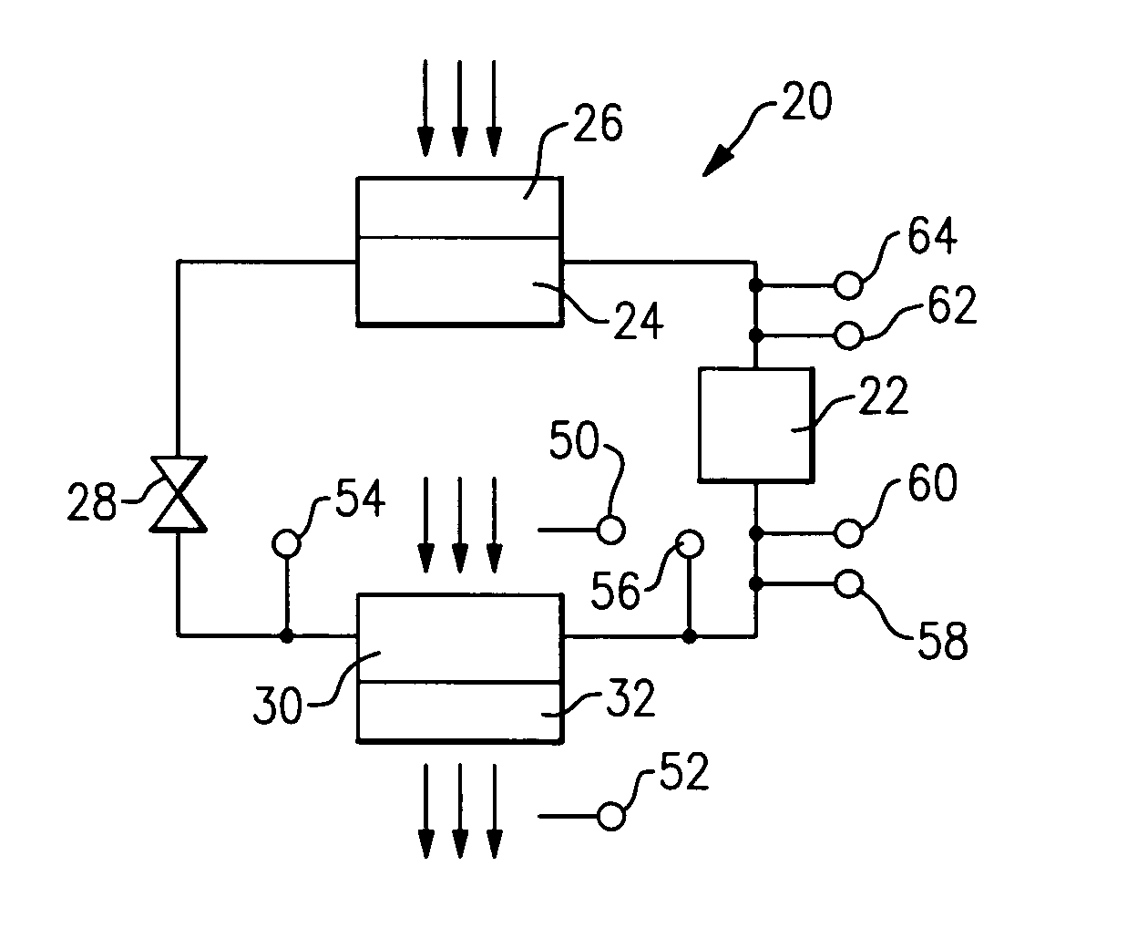
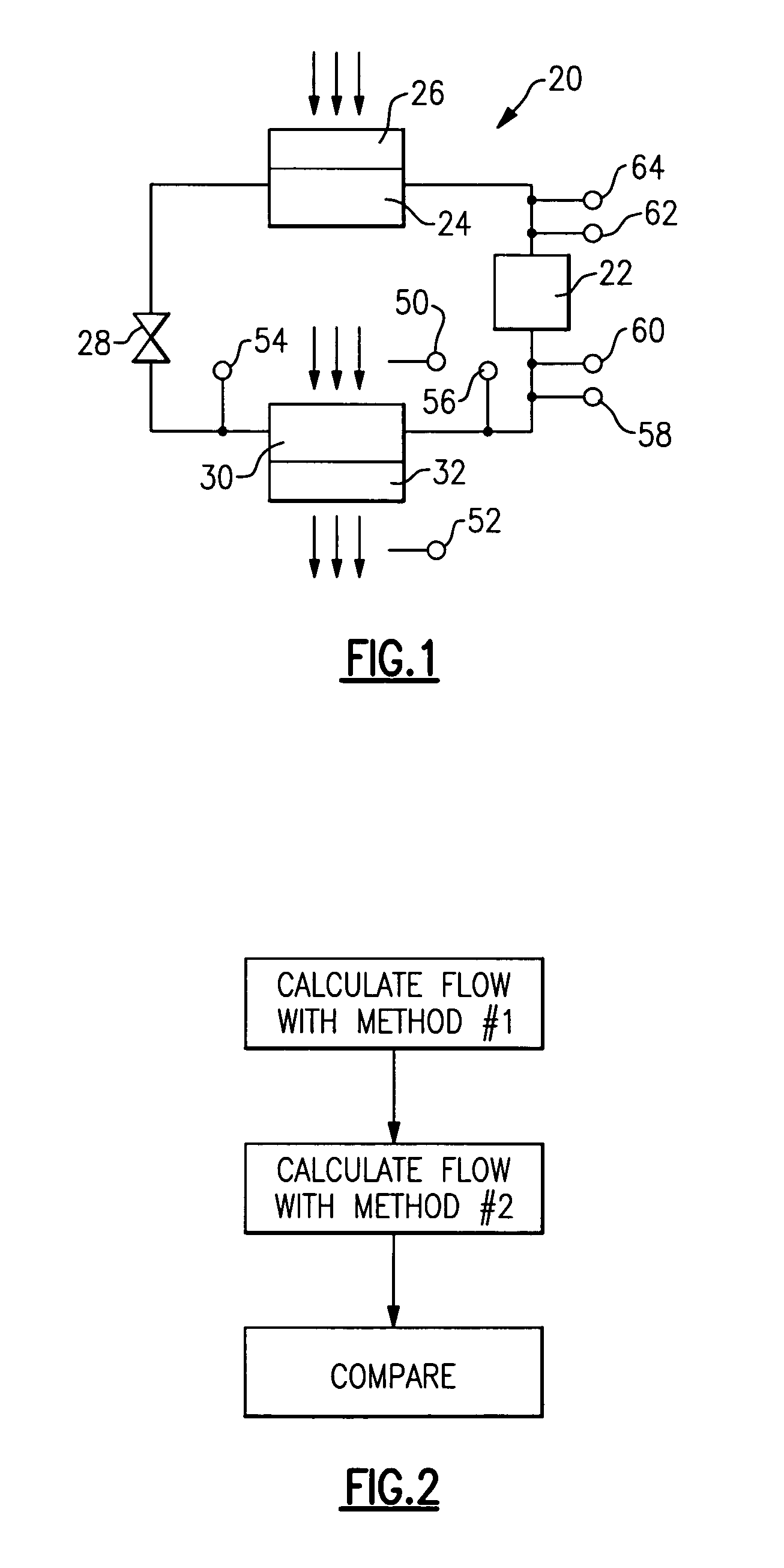
[0011]FIG. 1 shows a refrigerant system 20 incorporating a compressor 22 for compressing refrigerant and delivering it to a condenser 24. A fan 26 drives air over the condenser, and in an air conditioning mode, removes heat from the refrigerant in the condenser. Downstream of the condenser 24 is an expansion device 28. In complex systems, this expansion device may be electronically controlled with a closed feedback loop based upon a super heat temperature of the refrigerant approaching the compressor 22.

[0012]Downstream of the expansion device 28 is an evaporator 30 having a fan 32 for pulling air over the evaporator 30 and into an environment to be conditioned. Temperature readings may be taken on the air approaching the evaporator by sensor 50, the air having passed over the evaporator by sensor 52, the refrigerant approaching the evaporator by sensor 54, the refrigerant downstream of the evaporator by sensor 56, the pressure of the refrigerant approaching the compressor by sensor...


PUM

PropertyMeasurementUnit
mass flow ratesaaaaaaaaaa
mass flow rateaaaaaaaaaa
pressure ratioaaaaaaaaaa

Abstract

A refrigerant system is provided with a method and a control programmed to perform the method, in which a low charge of refrigerant is identified. The mass flow of refrigerant through the system is calculated utilizing at least two different methods. The two calculated mass flow rates are compared, and if they differ by more than predetermined amount, a determination is made that there is a low charge of refrigerant within the system.

Description

BACKGROUND OF THE INVENTION[0001]This invention relates to a simple method and control for identifying a low charge of refrigerant in a refrigerant system.[0002]Refrigerant systems are utilized to condition an environment and may include air conditioners or heat pumps. In a traditional refrigerant system, refrigerant is routed between several components through sealed connections. Over time, and for various reasons, some of the refrigerant may escape the sealed system. This can result in there being a lower charge of refrigerant than would be desirable.[0003]When there is a low charge of refrigerant, it becomes more difficult for the system to provide its function such as cooling air being directed into an environment. Additional load is put on the compressor, and the compressor may fail, or the system may not adequately condition the air being directed into the environment.[0004]Thus, various methods have been utilized to identify a low charge of refrigerant. One simple method look...

Claims


Application Information

Patent Timeline
Patent Type & Authority Patents(United States)
IPC IPC(8): F25B49/00F25B45/00G01K13/00
CPCF25B49/005F25B2500/19F25B2500/24F25B2700/13F25B2700/1931F25B2700/1933F25B2700/21151F25B2700/21152F25B2700/21172F25B2700/21173F25B2700/21174F25B2700/21175
Inventor KANG, PENGJUFARZAD, MOHSENFINN, ALAN M.SADEGH, PAYMAN
Owner CARRIER CORP
Features
  • R&D
  • Intellectual Property
  • Life Sciences
  • Materials
  • Tech Scout
  • Unparalleled Data Quality
  • Higher Quality Content
  • 60% Fewer Hallucinations
Learn More