High-strength ratchet structure for ratchet wrench

Inactive Publication Date: 2008-06-03
CHAN FU YI
View PDF5 Cites 17 Cited by
  • Summary
  • Abstract
  • Description
  • Claims
  • Application Information

AI Technical Summary

Benefits of technology

[0005]The present invention has been accomplished under the circumstances in view. It is the main object of the present invention to provide a high-strength ratchet structure for ratchet wrench, which is practical for high torque application. According to the present invention, the high-strength ratchet structure comprises a driving block, the driving block having a stepped axial hole cut through front and rear sides thereof, and two sliding grooves transversely formed on the front side and arranged in parallel at two sides of the stepped axial hole; two pairs of directional block members respectively movably mounted in the sliding grooves of the driving block; two spring members respectively mounted in the sliding grooves of the driving block and respectively supported between the associating directional block members; a ratchet member coupled to the driving block, the ratchet member having an axial screw hole and a plurality of teeth arranged around the inside wall thereof; a hollow screw bolt mounted in the stepped axial hole of the driving block and threaded into the axial screw hole of the ratchet member to secure

Problems solved by technology

This single-sided stop control design is not applicable for high torque application.
The ratchet member may slip when encountering a high resistance, resulting in a failure.

Method used


Image

  • High-strength ratchet structure for ratchet wrench
  • High-strength ratchet structure for ratchet wrench
  • High-strength ratchet structure for ratchet wrench

Examples


Embodiment Construction

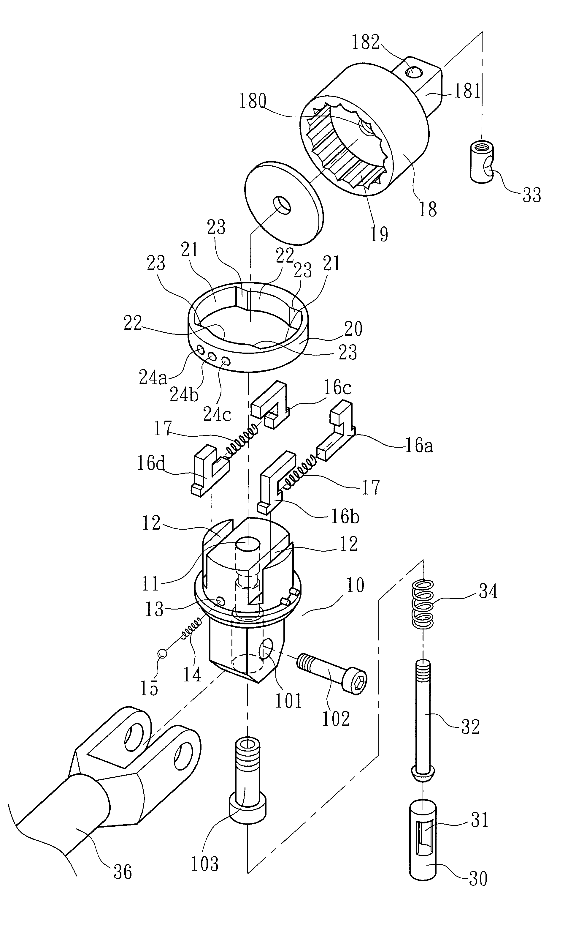
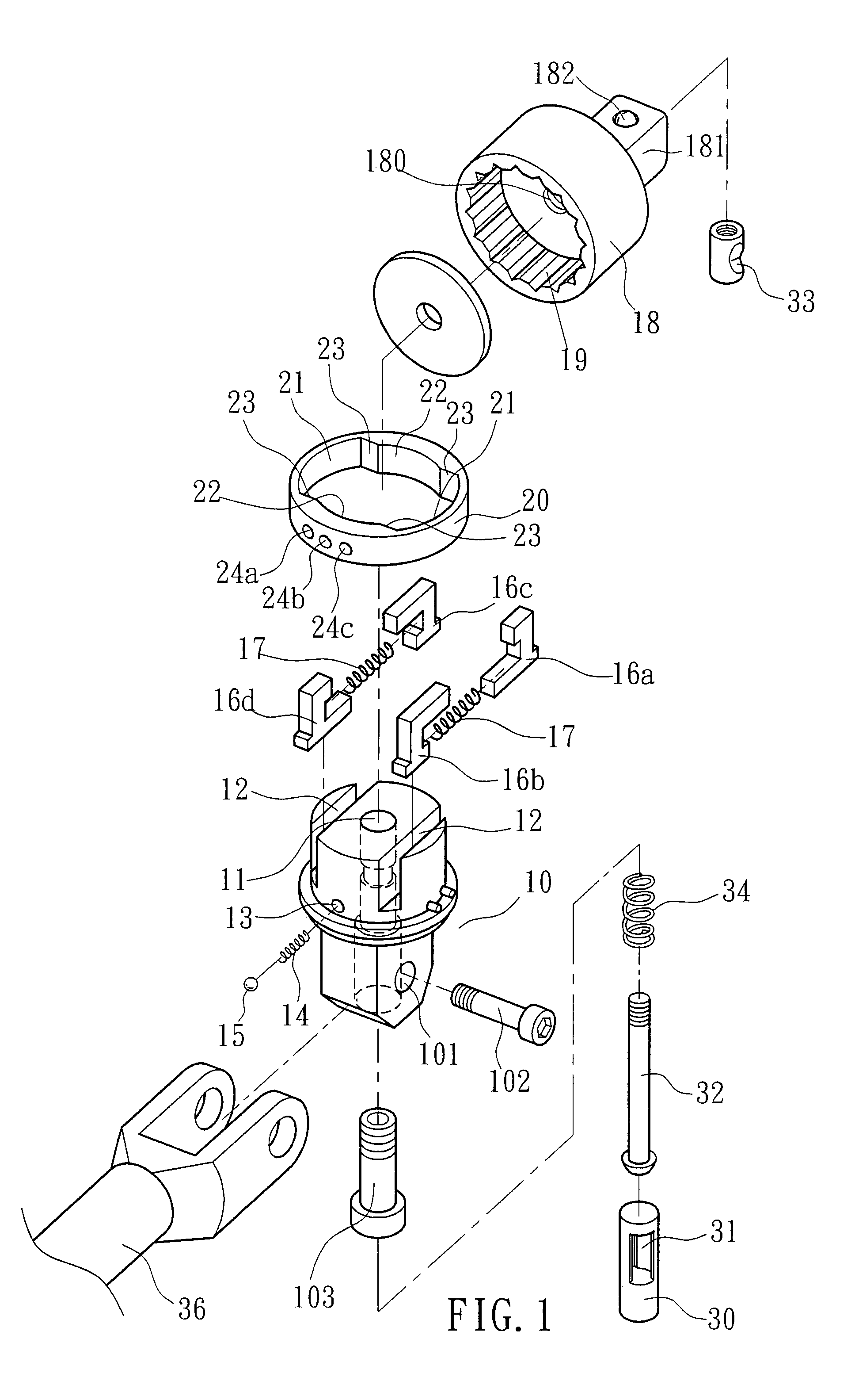
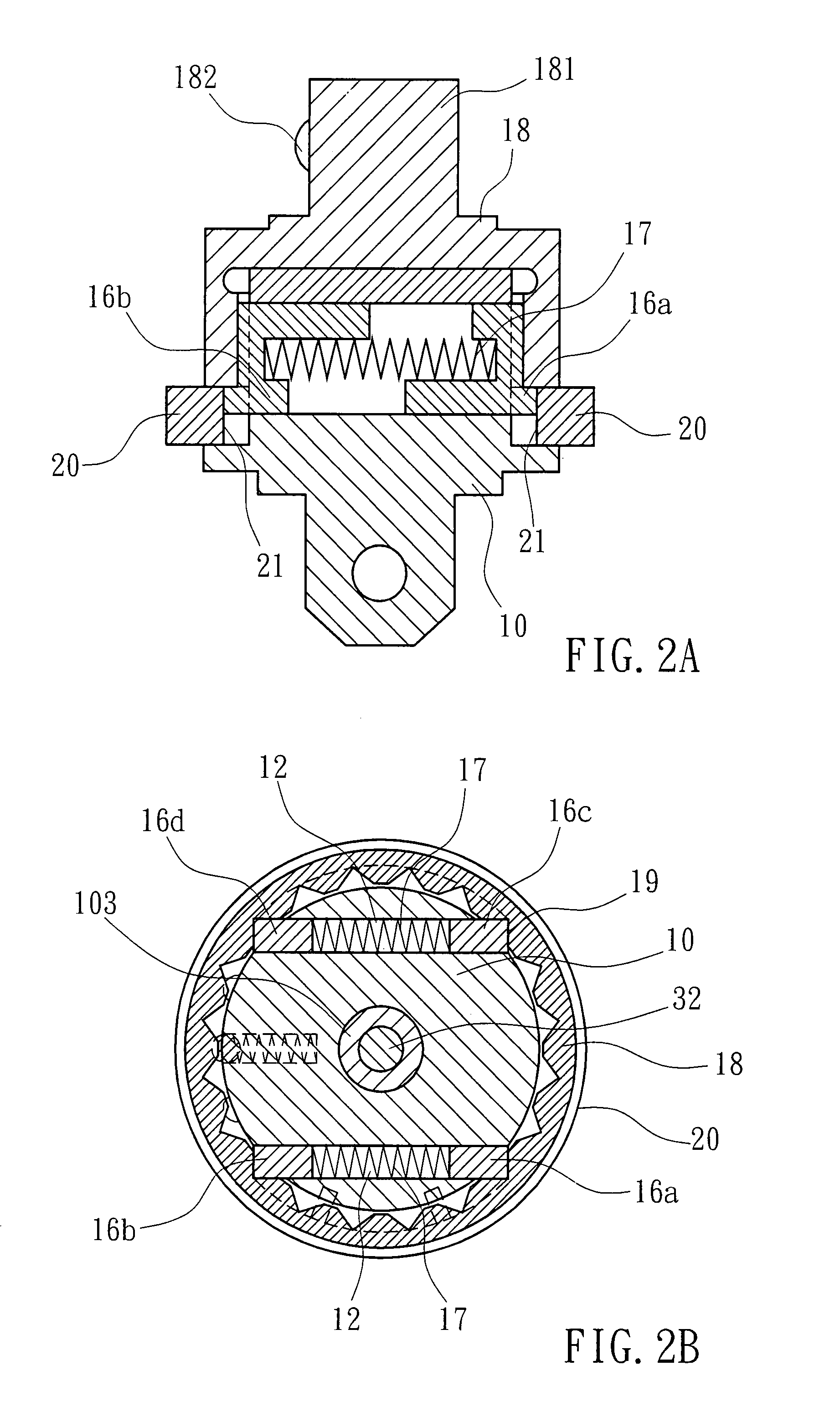
[0016]Referring to FIGS. 1˜7, a high-strength ratchet structure for ratchet wrench in accordance with the present invention is shown comprising a driving block 10. The driving block 10 has a stepped axial hole 11 cut through the top and bottom sides thereof, a pivot hole 101 transversely extending through its one end across the stepped axial hole 11 and pivotally connected to a swivel rod 36 with a pivot bolt 102, two sliding grooves 12 transversely arranged on its other end at two sides of the stepped axial hole 11, a side blind hole 13 extending in direction perpendicular to the extending direction of the stepped axial hole 11 and equally spaced from the sliding grooves 12 for accommodating a spring member 14 and a steel ball 15. The steel ball 15 is supported on one end of the spring member 14 and partially protruding over the periphery of the driving block 10. Two directional block members 16a and 16b, or 16c and 16d are respectively slidably mounted in the sliding grooves 12 of...


PUM


Abstract

A high-strength ratchet structure for ratchet wrench is disclosed to include a driving block with two transverse sliding grooves, two pairs of directional block members respectively movably mounted in the sliding grooves of the driving block, two spring members respectively mounted in the sliding grooves and supported between the associating directional block members, a ratchet member coupled to the driving block, and a direction control ring selectively set in a first position where the ratchet member is locked to the driving block, a second position where the ratchet member is prohibited from clockwise rotation relative to the driving block and allowed for counter-clockwise rotation relative to the driving block, or a third position where the ratchet member is prohibited from counter-clockwise rotation relative to the driving block and allowed for clockwise rotation relative to the driving block.

Description

BACKGROUND OF THE INVENTION[0001]1. Field of the Invention[0002]The present invention relates to ratchet wrench and more specifically, to a high-strength ratchet structure for ratchet wrench.[0003]2. Description of the Related Art[0004]Many reversible ratchet wrenches are commercially available. These reversible ratchet wrenches commonly comprise a wrench body, a ratchet member coupled to the wrench body, a directional block member for engaging the ratchet member to control the direction of rotation of the ratchet member relative to the wrench body, prohibiting the ratchet member from clockwise rotation and allowing the ratchet member for counter-clockwise rotation, or prohibiting the ratchet member from counter-clockwise rotation and allowing the ratchet member for clockwise rotation. This single-sided stop control design is not applicable for high torque application. The ratchet member may slip when encountering a high resistance, resulting in a failure.SUMMARY OF THE INVENTION[00...

Claims


Application Information

Patent Timeline
IPC IPC(8): B25B13/46B25B23/16
CPCB25B13/465B25B23/0028B25B23/0035B25G1/063
Inventor CHAN, FU-YI
Owner CHAN FU YI
Why Eureka
Try Eureka