Eureka AIR delivers breakthrough ideas for toughest innovation challenges, trusted by R&D personnel around the world.

X-ray apparatus and mammographic x-ray apparatus with an indicator

a technology of x-ray apparatus and indicator, which is applied in the field of x-ray apparatus, to achieve the effect of eliminating the deflecting beam and reducing the effor

Inactive Publication Date: 2008-06-03
SIEMENS AG
View PDF11 Cites 14 Cited by
  • Summary
  • Abstract
  • Description
  • Claims
  • Application Information

AI Technical Summary

Benefits of technology

[0007]The present embodiments relate to an X-ray apparatus and a mammographic X-ray apparatus with an indicator. The present embodiments may obviate one or more of the problems due to the limitations and disadvantages of the related art. For example, one exemplary embodiment illuminates the X-ray field, which precedes the actual making of the X-ray, in a way that is simple and involves little effort.
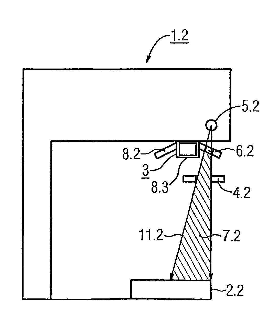
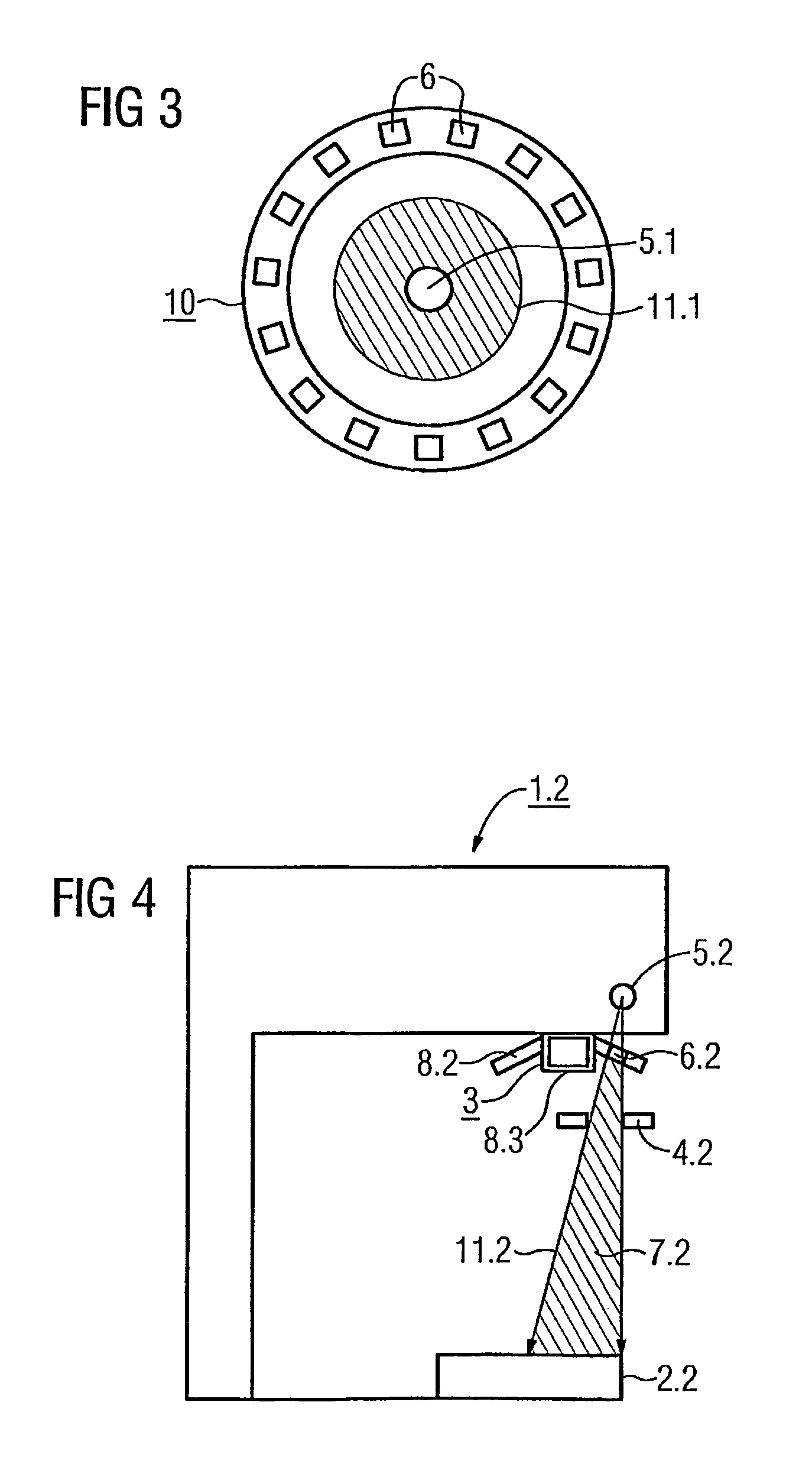
[0008]In one exemplary embodiment, an X-ray apparatus includes an X-ray beam generated by an X-ray source and a diaphragm. At least one LED is disposed as an indicator between the X-ray source and the diaphragm. The illuminating beam of the at least one LED is directed in an undeflected fashion onto the X-ray field, and the at least one LED is pivotable (swivable) out of the X-ray beam. The at least one LED is mounted on a filter array that is mounted between the X-ray source and the diaphragm. Accordingly, the diaphragm may not be used for shaping the beam of the X-ray beam and shaping the beam of the illuminating beam, and thus deflecting the illuminating beam can be eliminated. Complicated control of the orientation of the indicator means is eliminated, and a mirror that can be folded away is unnecessary, making a compact, low-maintenance construction possible.

Problems solved by technology

The present embodiments may obviate one or more of the problems due to the limitations and disadvantages of the related art.

Method used


Image

  • X-ray apparatus and mammographic x-ray apparatus with an indicator
  • X-ray apparatus and mammographic x-ray apparatus with an indicator
  • X-ray apparatus and mammographic x-ray apparatus with an indicator

Examples


Embodiment Construction

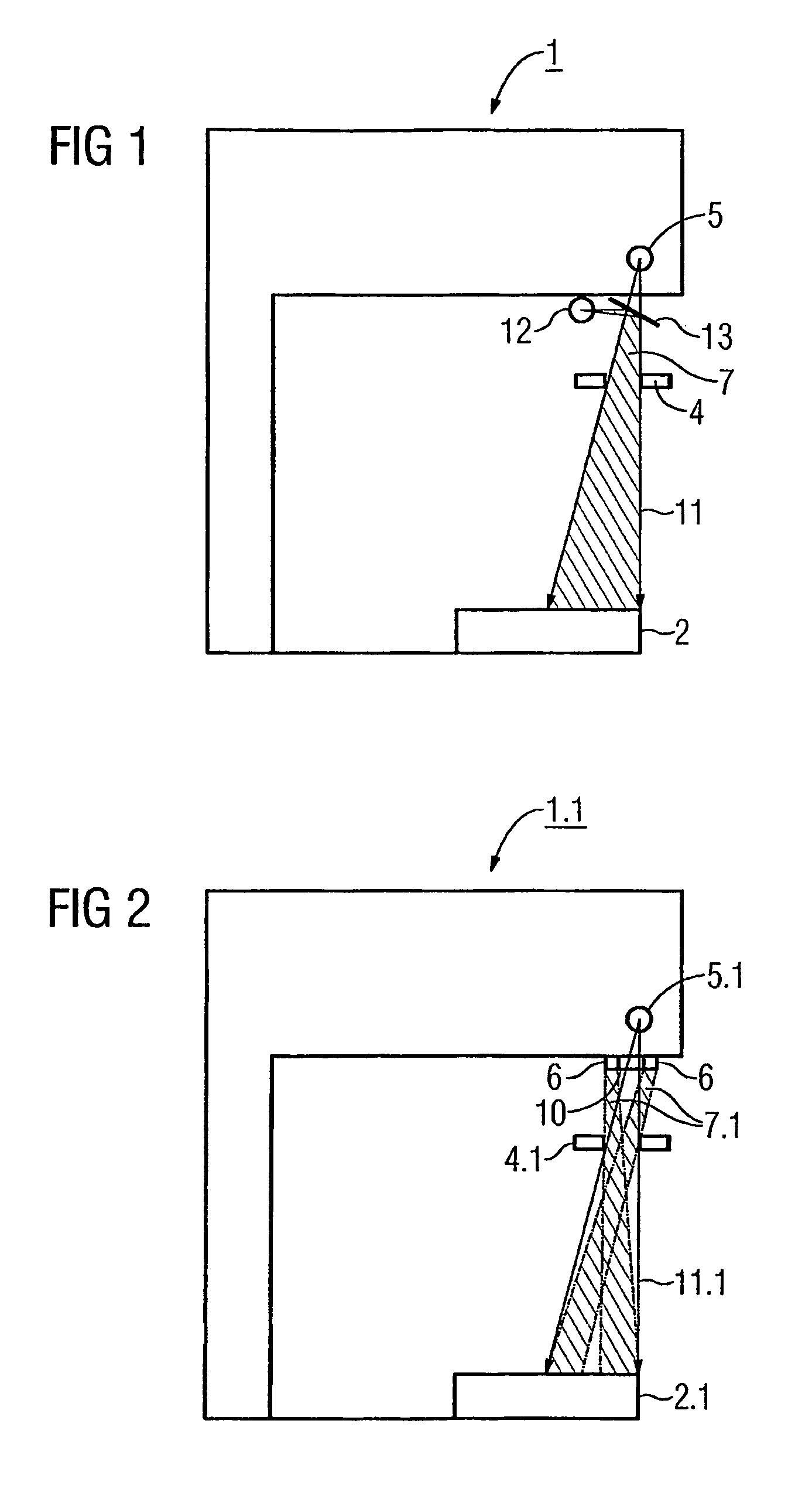
[0015]FIG. 1 shows a mammographic X-ray apparatus 1 according to the prior art. The mammographic X-ray apparatus 1 includes both an X-ray source 5 and a detector, for example, an object table 2 equipped with an X-ray film. During an examination, the X-ray source 5 generates an X-ray beam 11 that projects an object (image) (not shown), of a patient, which is to be examined, onto the detector. The mammographic X-ray apparatus 1 includes a diaphragm 4 that limits the X-ray beam 11 by blanking out, collimating, or blocking some portions of the X-ray beam 11. Before an actual operation of making an X-ray image, an X-ray beam location on the surface of the patient or on the object table 2 is monitored by an illuminating beam 7 that is generated by an incandescent bulb 12. The illuminating beam 7 is deflected by a mirror 13 in the direction of the X-ray field. The incandescent bulb 12 and the mirror 13 are adjusted, so that the illuminating beam 7 and the X-ray beam 11 are substantially co...


PUM


Abstract

An X-ray apparatus and a mammographic X-ray apparatus are provided. The X-ray apparatus includes an X-ray beam generated by an X-ray source and a diaphragm. At least one LED is disposed as an indicator between the X-ray source and the diaphragm. The illuminating beam of the LED is directed in an undeflected fashion onto the X-ray field. The LED may be pivotable (swivable) out of the X-ray beam. The LED is mounted on a filter array that is mounted between the X-ray source and the diaphragm.

Description

[0001]The present patent document is a continuation of PCT Application Serial Number PCT / EP2005 / 052047, filed May 4, 2005, designating the United States, which is hereby incorporated by reference. The present patent document also claims the benefit of foreign application number DE 10 2004 023 046.3 filed on May 11, 2004, which is hereby incorporated by reference.BACKGROUND[0002]1. Field[0003]The present embodiments relate to an X-ray apparatus, such as a mammographic X-ray apparatus. The apparatus includes an indicator.[0004]2. Related Art[0005]Generally, mammographic X-ray apparatuses have an indicator. Before the actual process of taking the X-ray images, the indicator projects an exemplary trace of an X-ray field on the surface of a patient body and / or on an object table. The X-ray field is monitored, for example, to assure that the correct diaphragm has been chosen. Conventionally, an incandescent bulb mounted laterally of the X-ray beam path is used. The beam of light from the ...

Claims


Application Information

Patent Timeline
Patent Type & Authority Patents(United States)
IPC IPC(8): A61B6/08A61B6/00
CPCA61B6/08A61B6/502
Inventor BRANDSTATTER, WERNERRAMSAUER, MARTIN
Owner SIEMENS AG
Why Eureka
Eureka Blog
Learn More