Mine door system with trigger-actuated latch mechanism

a technology of latch mechanism and trigger, which is applied in the direction of gas-proof doors, mechanical devices, and fastening means, etc., can solve the problems of movement of the stopping frame, jamming or unlatching of the door latch, and the movement of the door frame, etc., to facilitate the latching and unlatching of the door and the effect of less effort to opera

Active Publication Date: 2008-07-01
JACK KENNEDY METAL PRODS & BUILDINGS
View PDF27 Cites 7 Cited by
  • Summary
  • Abstract
  • Description
  • Claims
  • Application Information

AI Technical Summary

Benefits of technology

[0004]Among the several objects of this invention may be noted the provision of an improved door system for a mine stopping including an improved latch mechanism for holding a door of the system tightly closed during a mine convergence; and the provision of such a door system wherein the latch mechanism requires less effort to operate and thereby facilitates latching and unlatching of the door.
[0005]In one aspect, apparatus of this invention is a door system for closing a doorway in a mine stopping. The system comprises a door hinged adjacent the doorway for swinging relative to the stopping between a closed position and an open position swung outwardly away from the stopping, and a keeper mounted in fixed position relative to the doorway. The system further comprises a trigger-actuated latch mechanism including a detent engageable with the keeper for latching the door in its closed position and a trigger operably connected to the detent in a latched position. The mechanism is constructed and configured so that actuation of the trigger causes the detent to move from a latched position in which the detent engages the keeper for latching the door closed to an unlatched position in which the detent is disengaged from the keeper for allowing the door to be opened.

Problems solved by technology

A problem is encountered, however, in providing a door for a stopping because the floors of passages in mines often heave up or otherwise shift (sometimes referred to as a “convergence”), which may result in movement of the stopping and / or door frame.
Such convergence may cause the door latch to become jammed or become unlatched, which allows the door to open for undesired flow of air through the doorway.

Method used


Image

  • Mine door system with trigger-actuated latch mechanism
  • Mine door system with trigger-actuated latch mechanism
  • Mine door system with trigger-actuated latch mechanism

Examples


Embodiment Construction

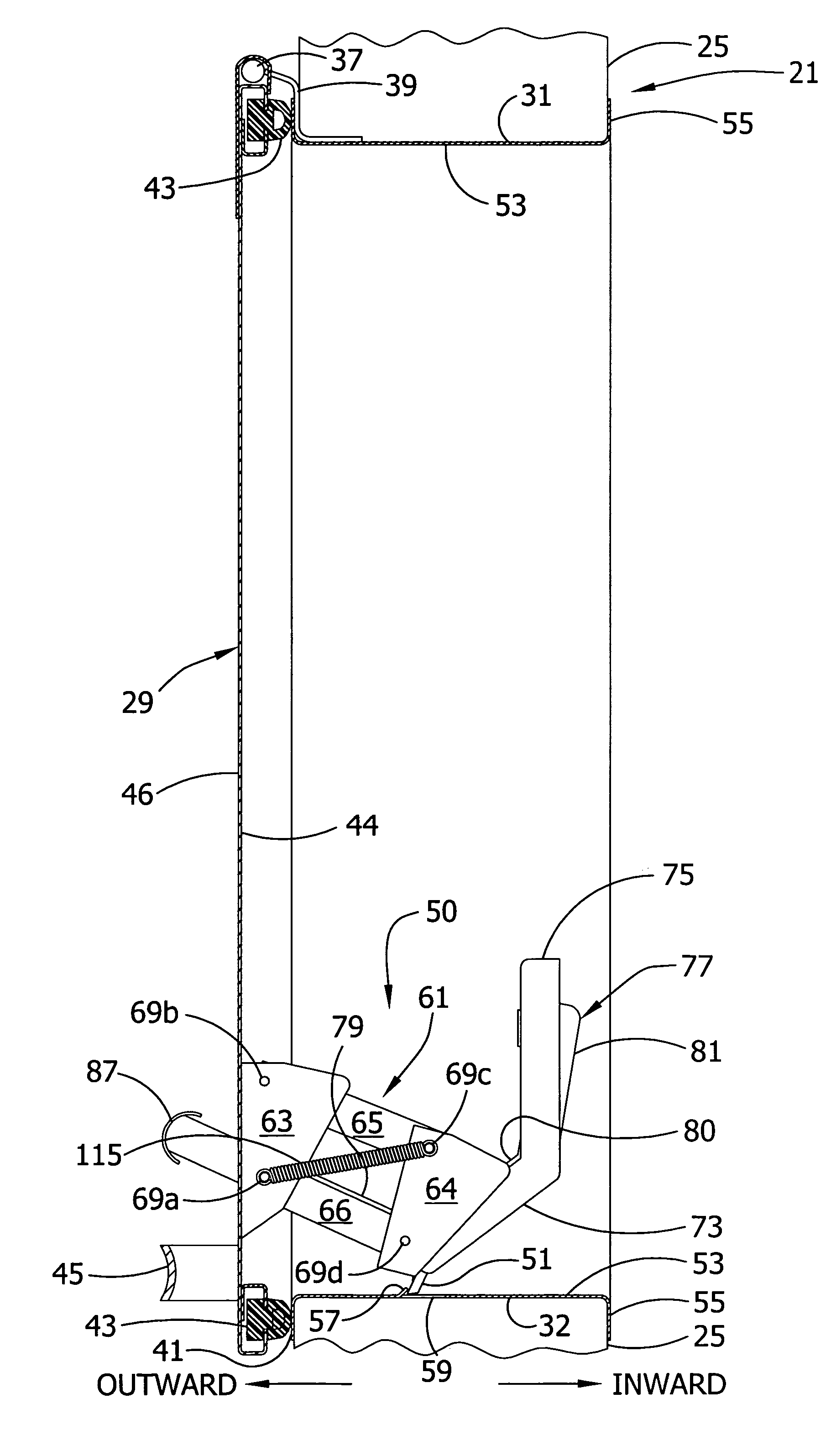
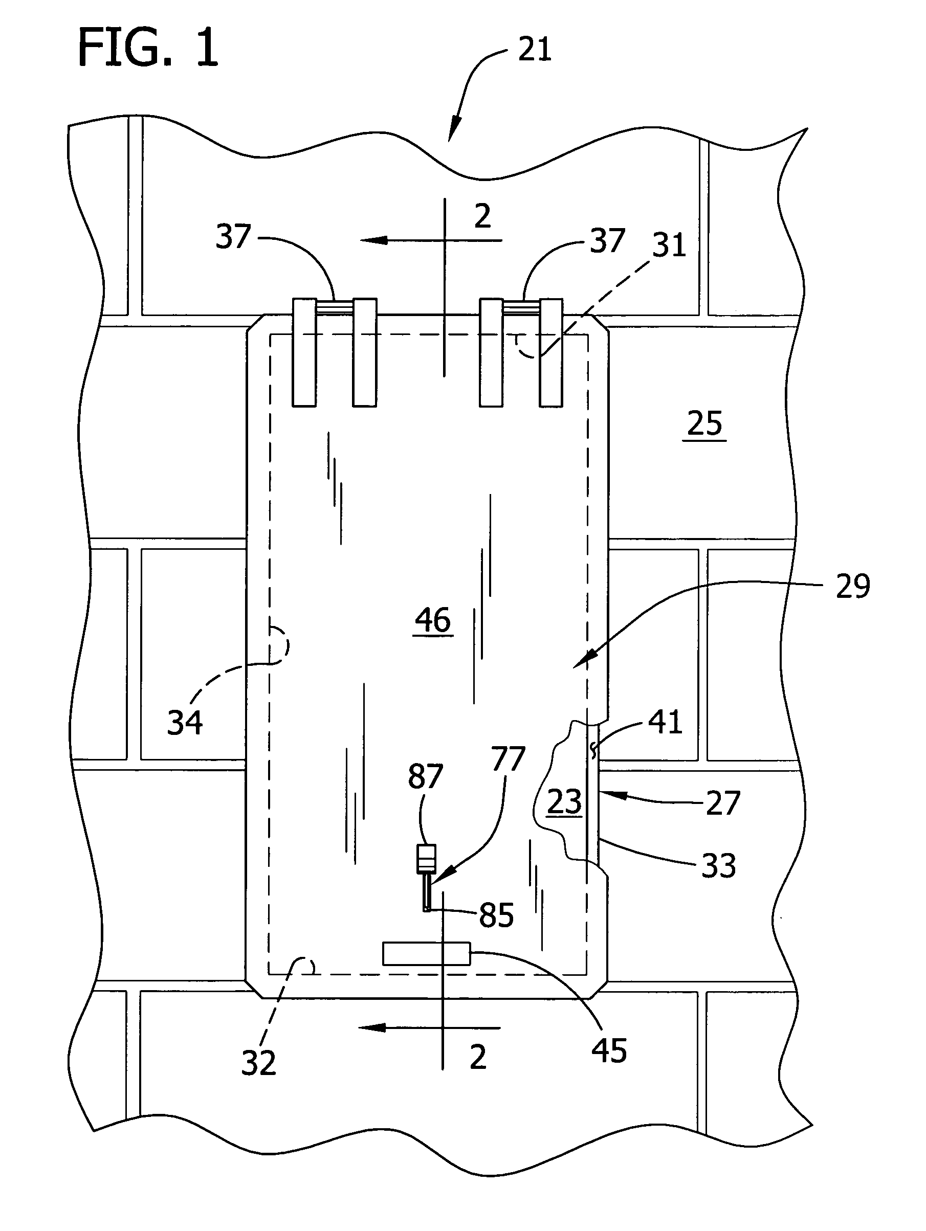
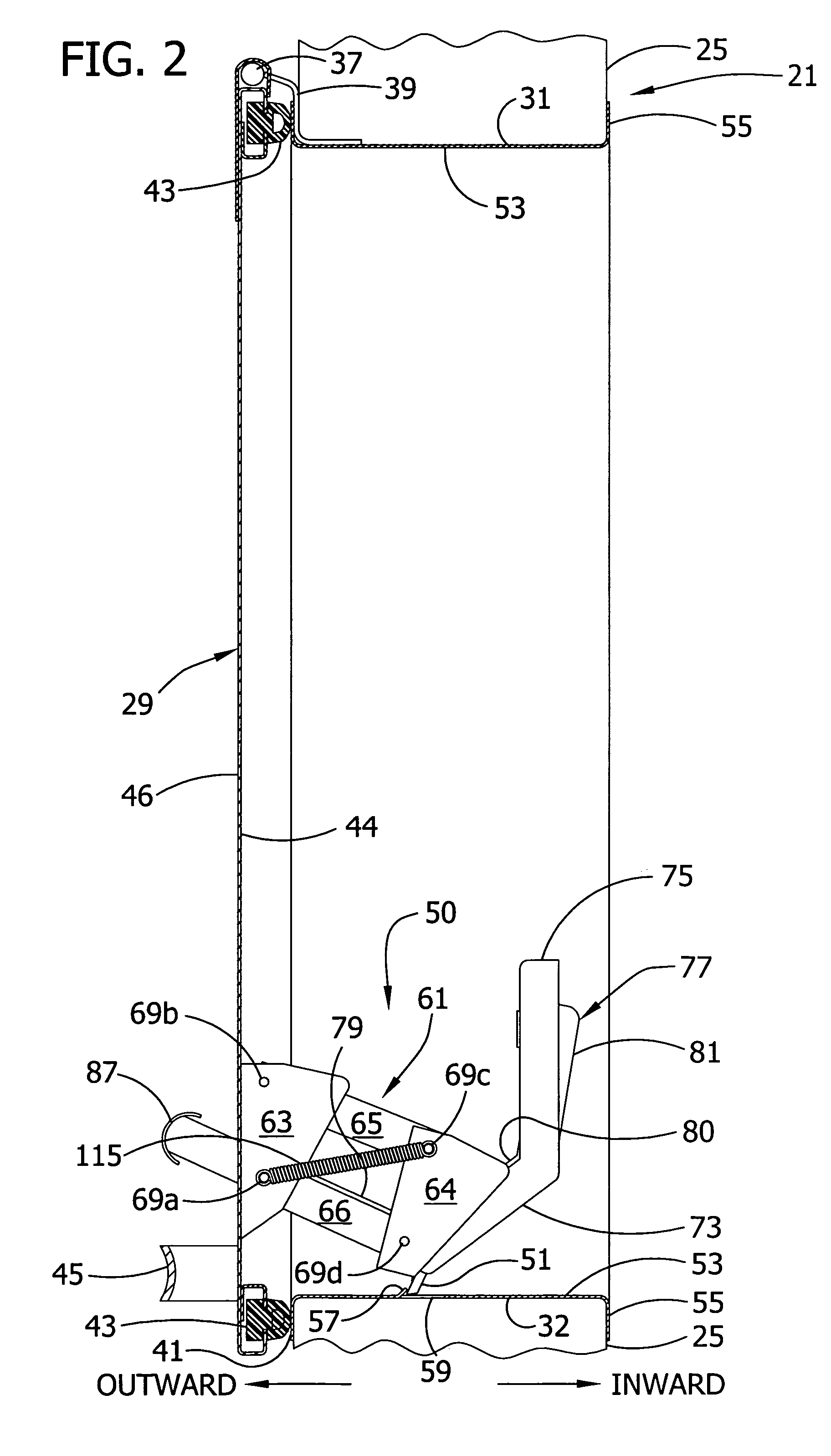
[0021]Referring now to the drawings, FIGS. 1-3 show a door system of the present invention generally designated 21, for closing a doorway 23 in a mine stopping 25. The door system 21 preferably includes a rectangular door frame, generally designated 27, and a door, generally designated 29, hinged on the door frame. The door frame 27 has opposing top and bottom horizontal frame members, designated 31 and 32, respectively, and two opposing vertical right and left side frame members, designated 33 and 34, respectively. The door 29 is supported at its upper end by horizontal hinge pins 37 mounted on brackets 39 secured to the top frame member. The door 29 swings on the hinge pin 37 relative to the door frame 27 between a closed position (FIGS. 1-3 and 5-6) engaging a face 41 of the frame around the doorway 23 and an open position (FIGS. 7-9) swung outwardly away from the frame. Preferably, a rubber seal 43 is attached to an inward face 44 of the door 29 for sealing against the frame fac...


PUM


Abstract

A mine door system for closing a mine doorway comprises a door hinged adjacent the doorway for swinging relative to the stopping between a closed position and an open position swung outwardly away from the stopping. A keeper is mounted in fixed position relative to the doorway. The system further comprises a trigger-actuated latch mechanism including a detent engageable with the keeper for latching the door in its closed position and a trigger operably connected to the detent in a latched position. The mechanism is constructed and configured so that actuation of the trigger causes the detent to move from a latched position in which the detent engages the keeper for latching the door closed to an unlatched position in which the detent is disengaged from the keeper for allowing the door to be opened.

Description

BACKGROUND OF THE INVENTION[0001]This invention relates generally to doors for mine stoppings and more particularly to latch mechanisms for such doors.[0002]Stoppings are widely used in mines to block off the flow of air through some mine passageways. It is often desired that such stoppings be provided with a door for occasional access to the blocked-off passageway. A problem is encountered, however, in providing a door for a stopping because the floors of passages in mines often heave up or otherwise shift (sometimes referred to as a “convergence”), which may result in movement of the stopping and / or door frame. Such convergence may cause the door latch to become jammed or become unlatched, which allows the door to open for undesired flow of air through the doorway.[0003]The doors disclosed in applicants' U.S. Pat. Nos. 4,082,331 and 6,032,986, incorporated herein by reference, address the aforementioned problem and offer generally satisfactory solutions. The present invention, how...

Claims


Application Information

Patent Timeline
Patent Type & Authority Patents(United States)
IPC IPC(8): E05B63/20E05B63/22E05C1/10E05C3/06E05C3/14E05C3/16E06B5/14E21F1/10E21F17/12
CPCE05C1/10E05B63/22Y10T292/54Y10T292/1053Y10T292/1051
Inventor KENNEDY, WILLIAM R.KENNEDY, JOHN M.
Owner JACK KENNEDY METAL PRODS & BUILDINGS
Why Eureka
Try Eureka