Female electrical contact element and method for making a female electrical contact element

a technology of electrical contact elements and female terminals, which is applied in the direction of electrically conductive connections, coupling device connections, electrical apparatus, etc., can solve the problems of difficult female terminals, and achieve the effect of simple and inexpensive manufacturing

Inactive Publication Date: 2008-07-01
SOURIAU
View PDF30 Cites 13 Cited by
  • Summary
  • Abstract
  • Description
  • Claims
  • Application Information

AI Technical Summary

Problems solved by technology

However, such a female terminal is difficult to make inasmuch as the terminal is formed of three independent parts that are integral with each other.

Method used


Image

  • Female electrical contact element and method for making a female electrical contact element
  • Female electrical contact element and method for making a female electrical contact element

Examples


Embodiment Construction

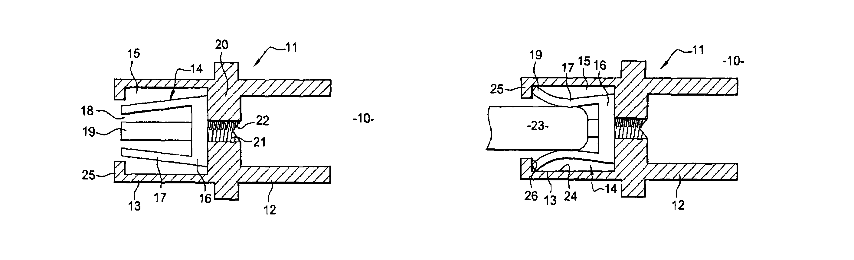
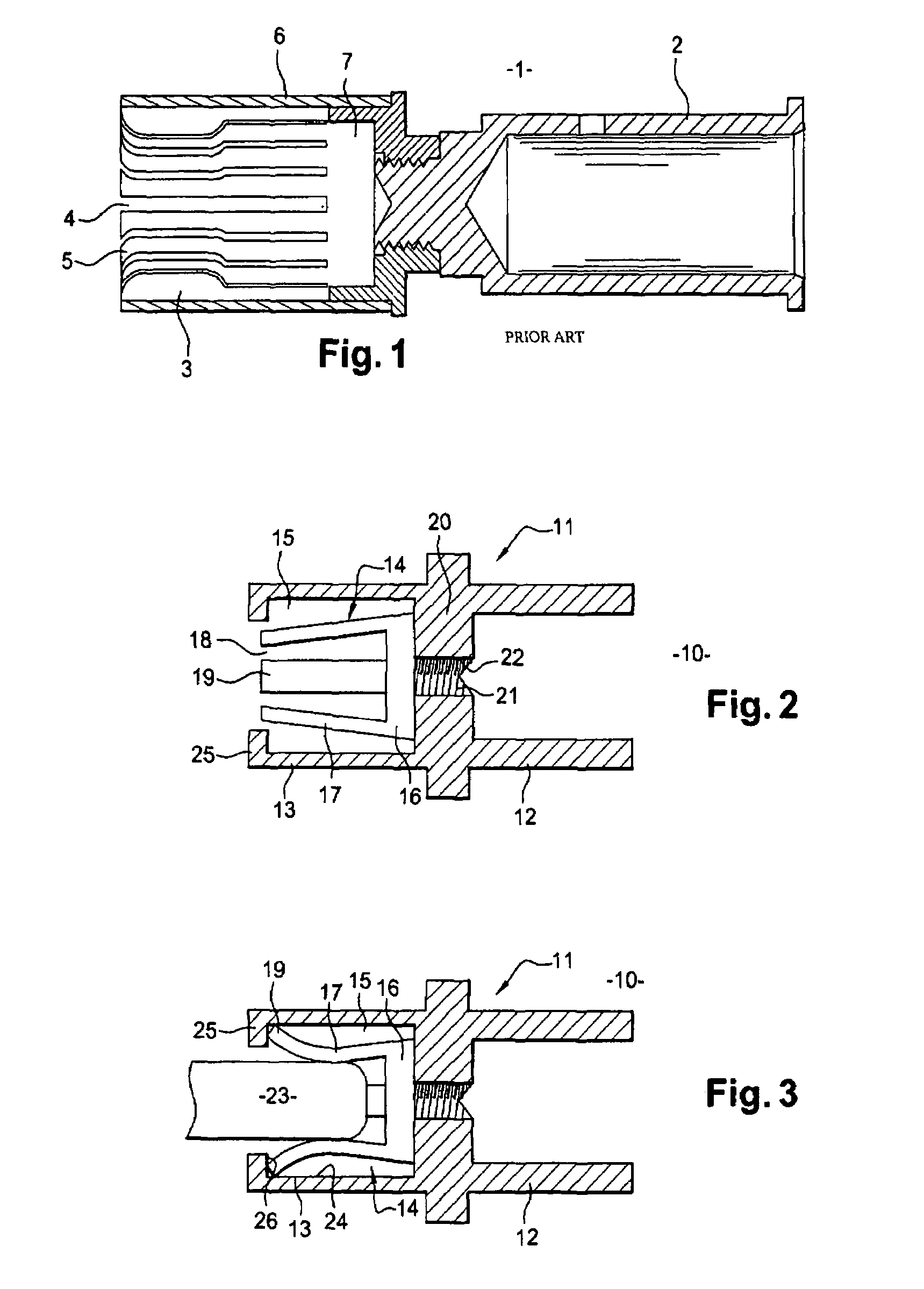
[0032]FIG. 2 represents a female contact element 10 according to an example of embodiment of the invention.

[0033]The female contact element 10 comprises two distinct parts. A first part 11 is equipped with a body in a generally cylindrical tube shape in which are arranged a rear shank 12 and a front shank 13. The rear shank 12 is, for example, designed to be crimped on an electric cable. The front shank 13 is designed to receive a complementary male contact element in a generally cylindrical shape (not represented in FIG. 2). For this purpose, an elastic socket 14, forming the second part of the contact element 10, is fixed mounted in a cavity 15 of the front shank 13. The rear shank 12 and the front shank 13 are separated from each other by a transverse wall 20, diametrically traversing the first part 11. The transverse wall 20 forms the bottom of the rear shank 12 and the front shank 13.

[0034]The elastic socket 14, housed in the front shank 13, comprises a base 16 from which a plu...


PUM


Abstract

The female contact element comprising a rear shank designed to receive an electrical conductor and a front shank equipped with an elastic socket designed to receive a male contact element. The female contact element is formed from a one-piece tubular body in which the front shank and the rear shank are arranged, the elastic socket being fixed mounted in the front shank. A method for manufacturing such a female contact element.

Description

RELATED APPLICATION[0001]This application claims priority to French Application No. FR 05 52433 filed Aug. 4, 2005.TECHNICAL FIELD[0002]The invention relates to a female electrical contact element able to convey a high current flow. The invention also relates to a method of making such a female electrical contact element. The invention finds applications particularly in the field of electrical connectors designed to be utilized under severe conditions, for example in the field of avionics where temperature and vibration conditions may be extreme.BACKGROUND ART[0003]A female electrical contact element comprising an elastic holding element that is able to maintain in position a male electrical contact element in a generally cylindrical form is already known.[0004]In particular, a female contact element in three parts is known from document FR 2 692 080, such as represented in FIG. 1 of the prior art. A first part is comprised of a rear shank 2 designed to receive an electrical conduct...

Claims


Application Information

Patent Timeline
Patent Type & Authority Patents(United States)
IPC IPC(8): H01R13/02
CPCH01R13/187H01R4/06H01R13/111
Inventor RIBEAU, PASCALDECHANTELOUP, JEAN-MICHEL
Owner SOURIAU
Why Eureka
Try Eureka