Clip for heat dissipation device

a heat dissipation device and clip technology, applied in semiconductor devices, semiconductor/solid-state device details, cooling/ventilation/heating modifications, etc., can solve the problems of socket boards, difficult to attach and detach the clip, and time-consuming installation and removal of clips

Inactive Publication Date: 2008-07-08
HON HAI PRECISION IND CO LTD +1
View PDF8 Cites 15 Cited by
  • Summary
  • Abstract
  • Description
  • Claims
  • Application Information

AI Technical Summary

Problems solved by technology

Therefore, it is troubling and time-consuming to install or remove the clip 10.
This makes it difficult to attach and detach the clip 10 from the socket board 40.

Method used


Image

  • Clip for heat dissipation device
  • Clip for heat dissipation device
  • Clip for heat dissipation device

Examples


Embodiment Construction

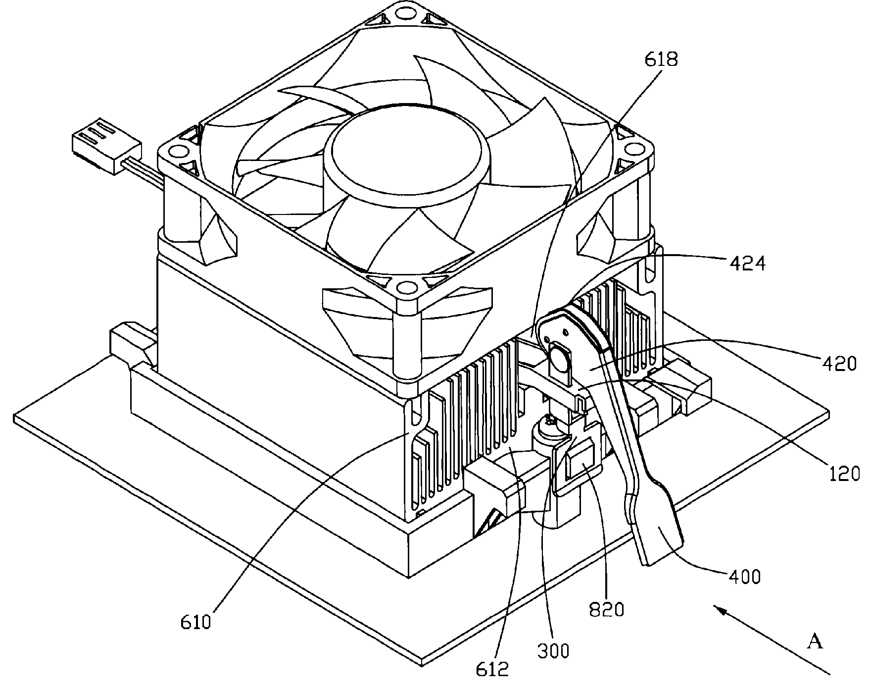
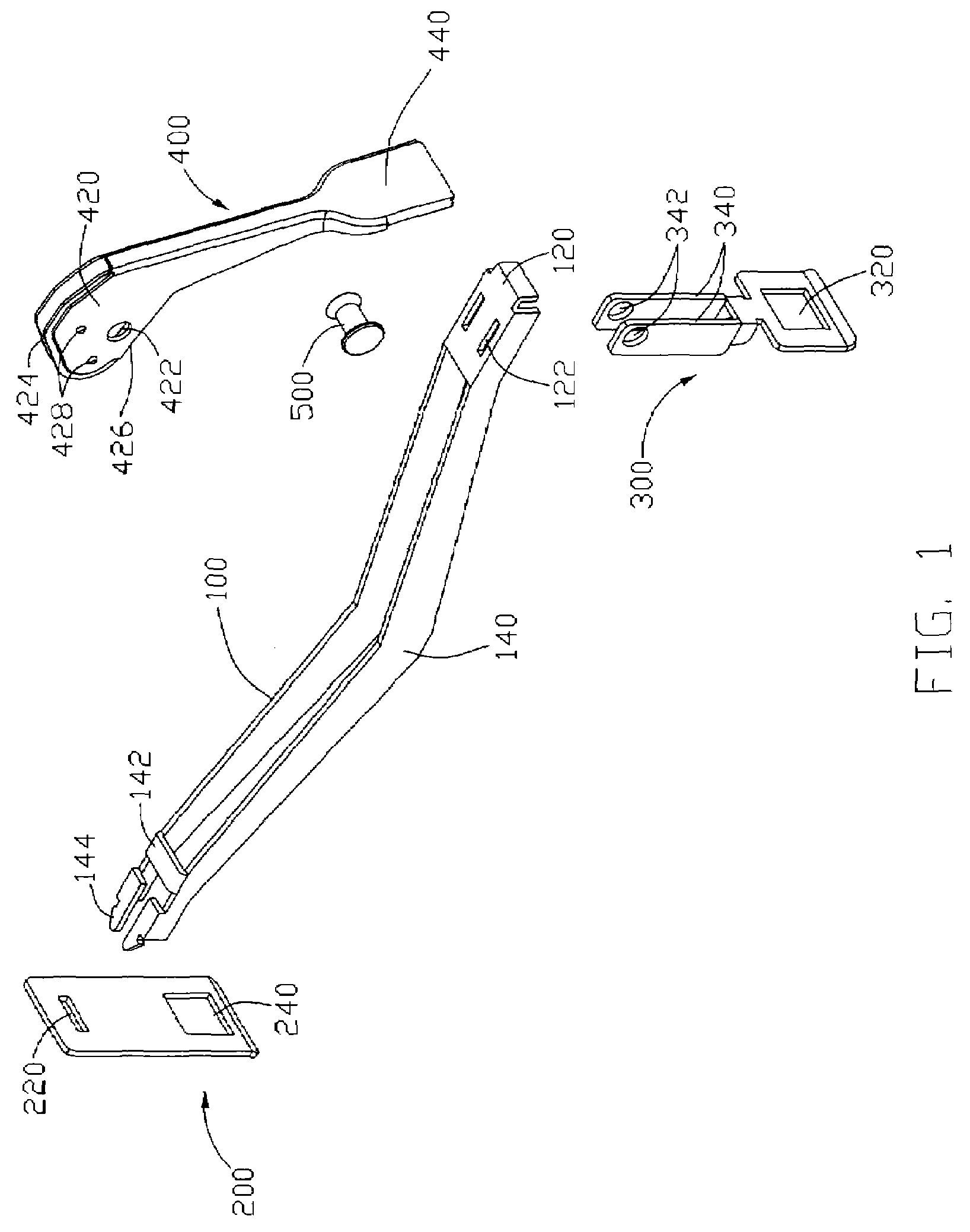
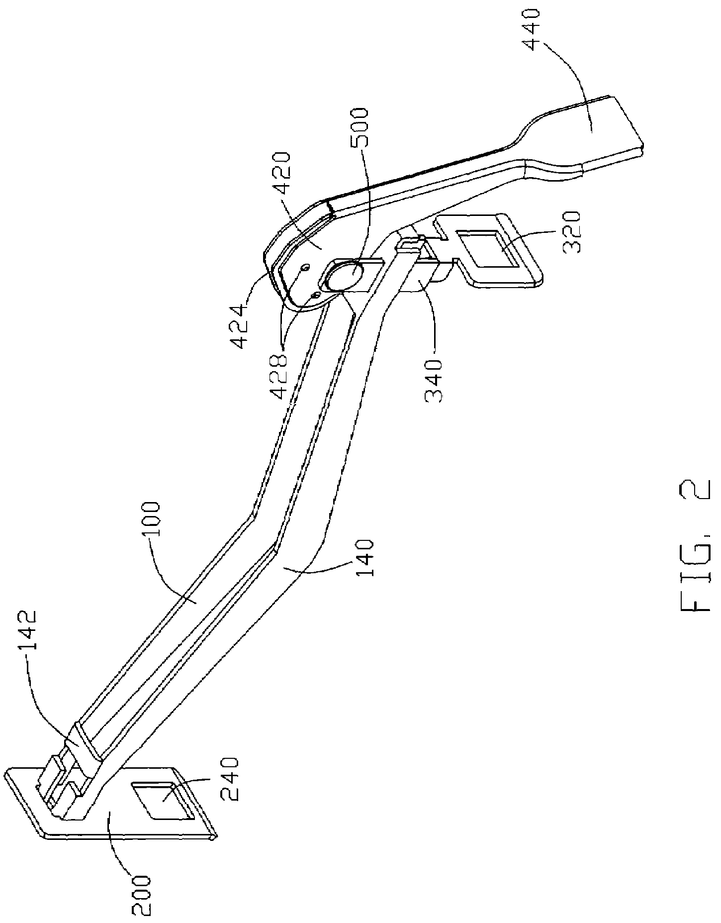
[0016]Referring to FIGS. 1-2, a clip in accordance with a preferred embodiment of the present invention is illustrated. The clip is used to secure a heat sink to an electronic package; it comprises an elongated body 100, a first hook plate 200, a second hook plate 300, and an actuating member 400.

[0017]The body 100 comprises a flat supporting portion 120 and a pair of spaced V-shaped arms 140 extending from opposite sides of the supporting portion 120. A pair of spaced slots 122 are defined through the supporting portion 120, and extend along a direction substantially in line with the two arms 140. A bridge 142 is formed at the arms 140 adjacent a free end of the body 100 distant from the supporting portion 120. The bridge 142 interconnects the arms 140 to reinforce the strength of the body 100. Each arm 140 has a barb 144 formed at the free end of the body 100 for engaging with the first hook plate 200 to fasten the body 100 to the first hook plate 200.

[0018]The first hook plate 20...


PUM


Abstract

A clip includes a body, an actuating member, a first hook plate and a second hook plate. The body includes a supporting portion and a pair of spaced arms extending from opposite sides of the supporting portion. The actuating member includes a cam supported on the supporting portion. The first hook plate is detachably coupled to a distal end of the arms of the body. The second hook plate extends through the supporting portion and is pivotally coupled to the cam of the actuating member. The actuating member is turnable relative to the second hook plate between a locked position and an unlocked position.

Description

FIELD OF THE INVENTION [0001]The present invention relates to a clip for a heat dissipation device, more particularly to a clip which can readily and securely attach a pre-assembled heat dissipation device to an electronic device.DESCRIPTION OF RELATED ART [0002]A heat dissipation device is usually placed in thermal contact with an electronic package, such as a central processing unit (CPU), and transfers heat through conduction away from the electronic package to prevent over-heating of the electronic package. Usually a heat dissipation device is secured to an electronic package by a clip.[0003]Referring to FIG. 8, a clip 10 in accordance with related art secures a heat dissipation device 20 to a CPU module 30 fitting into a socket board 40. The heat dissipation device 20 comprises a heat sink 22 and a fan 24 mounted on an upper side of the heat sink 22. The clip 10 comprises a body 12 abutting against the heat sink 22 and a pair of legs 14 formed at opposite ends of the body 12. E...

Claims


Application Information

Patent Timeline
Patent Type & Authority Patents(United States)
IPC IPC(8): H05K7/20
CPCH01L23/4093H01L23/467H01L2924/0002H01L2924/00
Inventor CHEN, CHUN-CHIZHOU, SHI-WENCHEN, GUOWU, ZHAN
Owner HON HAI PRECISION IND CO LTD
Why Eureka
Try Eureka