System and method for turbine engine adaptive control for mitigation of instabilities

a technology of adaptive control and turbine engine, which is applied in the field of control systems for turbine engines, can solve the problems of turbine engine damage, combustion driven instabilities are the natural resonance of the combustor, and the risk of combustion driven instabilities, so as to and reduce the instabilities of the combustor

Inactive Publication Date: 2008-08-05
HONEYWELL INT INC
View PDF17 Cites 35 Cited by
  • Summary
  • Abstract
  • Description
  • Claims
  • Application Information

AI Technical Summary

Problems solved by technology

One issue in turbine engine performance and reliability is the risk of combustion driven instabilities.
In particular, oscillations of pressure in the turbine engine combustor can create control problems and possibly lead to turbine engine damage if allowed to continue.
One cause of combustion driven instabilities is the natural resonance of the combustor.
This causes variations in the fuel flow to the combustor, which in turn causes the flame in the combustor to modulate, creating more pressure ripples.
In some circumstances the natural resonant frequencies of the system will cause these pressure oscillations to constructively reinforce, leading to a potentially unacceptable level in pressure oscillations.
These types of combustion instabilities are particularly problematic in gaseous fuel turbine engines that are operated at high efficiency and low emission levels but can also exist in liquid fueled turbine engines.
Previous methods of compensating for these combustion instabilities have been limited.
Unfortunately this is not an acceptable solution for applications where the power output of the turbine engine must be tightly controlled for efficiency or low emission purposes.

Method used


Image

  • System and method for turbine engine adaptive control for mitigation of instabilities
  • System and method for turbine engine adaptive control for mitigation of instabilities
  • System and method for turbine engine adaptive control for mitigation of instabilities

Examples


Embodiment Construction

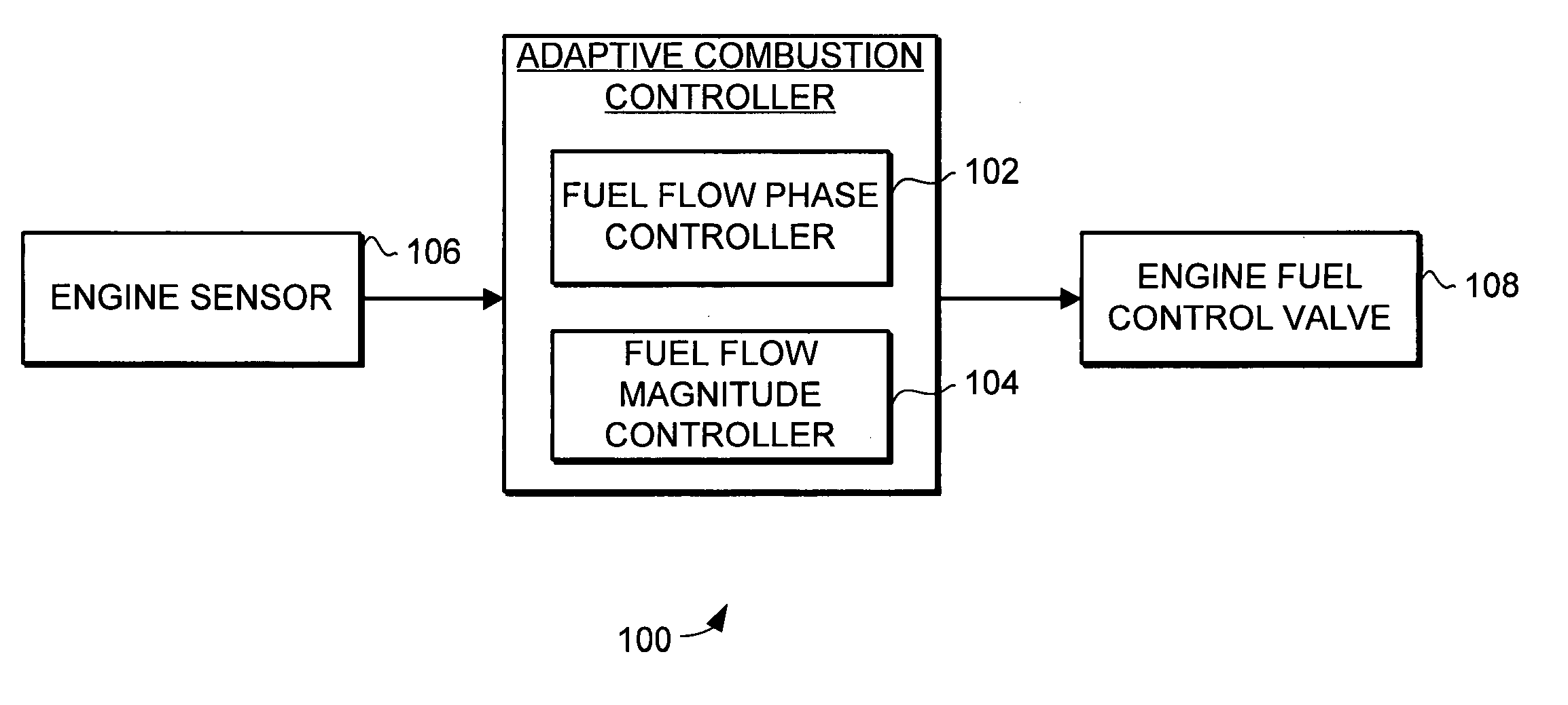
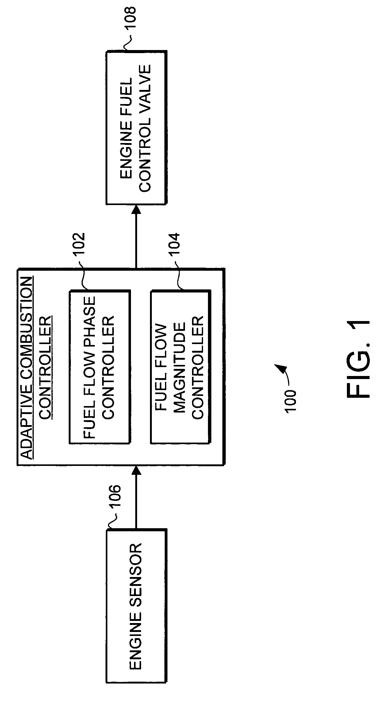
[0020]The present invention provides an adaptive combustion controller and method for a turbine engine. The adaptive combustion controller and method modulates the fuel flow to the turbine engine combustor to reduce combustion instabilities.

[0021]Turning now to FIG. 1, an adaptive combustion controller 100 is illustrated schematically. The adaptive combustion controller 100 includes a fuel flow phase controller 102 and a fuel flow magnitude controller 104. The adaptive combustion controller receives sensor data from an engine sensor 106. The adaptive combustion controller 100 modulates the fuel flow by adaptively controlling an engine fuel control valve 108 to reduce combustion instabilities. Specifically, in response to the sensor data the fuel flow phase controller 102 adjusts the phase of the modulated fuel flow to reduce instabilities in the combustor. Likewise, in response to the sensor data the fuel flow magnitude controller 104 adjusts the magnitude of the modulated fuel flow...


PUM


Abstract

The present invention provides an adaptive combustion controller and method for a turbine engine. The adaptive combustion controller and method modulates the fuel flow to the turbine engine combustor to reduce combustion instabilities. In particular, the adaptive combustion controller includes a fuel flow phase controller and a fuel flow magnitude controller. The adaptive combustion controller receives sensor data from the turbine engine. In response to the sensor data the fuel flow phase controller adjusts the phase of the modulated fuel flow to reduce instabilities in the combustor. Likewise, in response to the sensor data the fuel flow magnitude controller adjusts the magnitude of the modulated fuel flow to further reduce the instabilities in the combustor. By modulating the fuel flow to the combustor, and adaptively adjusting the phase and magnitude of the modulated fuel flow, the adaptive combustion controller is able to effectively reduce combustion instabilities.

Description

FIELD OF THE INVENTION[0001]This invention generally relates to turbine engines, and more specifically relates to control systems for turbine engines.BACKGROUND OF THE INVENTION[0002]Turbine engines are widely used for a variety of purposes. For example, turbine engines are commonly used as propulsion engines in aircraft and other large vehicles. Turbine engines are also used in power generation. For example, turbine engines are commonly used as auxiliary power units in aircraft to supply electric power and compressed air. Large turbine engines are also used in power plants for electricity generation. In all applications the reliability and performance of the turbine engine is of critical importance.[0003]One issue in turbine engine performance and reliability is the risk of combustion driven instabilities. In particular, oscillations of pressure in the turbine engine combustor can create control problems and possibly lead to turbine engine damage if allowed to continue. One cause o...

Claims


Application Information

Patent Timeline
Patent Type & Authority Patents(United States)
IPC IPC(8): F02C9/28
CPCF02C9/26
Inventor CRITCHLEY, IAN L.ANSON, BRUCECASPERMEYER, MATTHEW C.SCOTT, MIKE W.
Owner HONEYWELL INT INC
Why Eureka
Try Eureka