
Subsea well communications apparatus and method using variable tension large offset risers

a technology of offset risers and subsea wells, which is applied in the direction of sealing/packing, drilling pipes, and wellbore/well accessories, etc., can solve the problems of less economically feasible and economically desirable service of subsea wells, less economically feasible to employ dry tree strategies to service these wells, and relatively expensive tension leg and spar platforms. achieve the effect of positive tension

Active Publication Date: 2008-08-26
KELLOGG BROWN & ROOT LLC
View PDF4 Cites 44 Cited by
  • Summary
  • Abstract
  • Description
  • Claims
  • Application Information

AI Technical Summary

Benefits of technology

The present invention provides a dry tree apparatus for host production facilities that can be constructed using semi-submersible or mono-hulled platforms. The apparatus includes compliant production riser systems that can accommodate well service and maintenance activities. The invention also includes a plurality of variable tension risers that can connect to a single host production facility through a dry tree. The invention can be used in water of a sufficient depth to accommodate the curved geometry of the risers. The invention can be used on a variety of host platforms such as spar platforms, tension leg platforms, submersible platforms, and drillships. The method for installing the communications riser from a floating platform to a subsea wellhead can include deploying a wellhead connector, attaching a guide and ballast line, and manipulating the guide and ballast line to deflect the riser and lower it to engage the wellhead. The invention provides a more efficient and flexible means to communicate with subsea wells.

Problems solved by technology

Dry tree systems, in contrast, place the control devices on a floating platform out of the water, and are therefore relatively dry in nature.
Unfortunately, the placement of subsea wellheads within 90 meters (300 feet) of each other is not always feasible or economically desirable.
In these instances, it is often less economically feasible to employ dry tree strategies to service these wells as their spacing would require the installation of several tension leg or spar platforms.
Tension leg and spar platforms are relatively expensive endeavors, particularly because of the amount of anchoring and mooring required to maintain them in a relatively static position in rough waters.

Method used


Image

  • Subsea well communications apparatus and method using variable tension large offset risers
  • Subsea well communications apparatus and method using variable tension large offset risers
  • Subsea well communications apparatus and method using variable tension large offset risers

Examples


Embodiment Construction

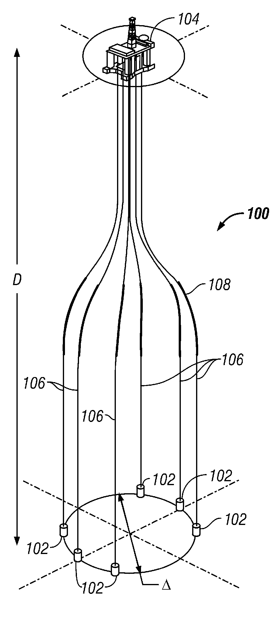
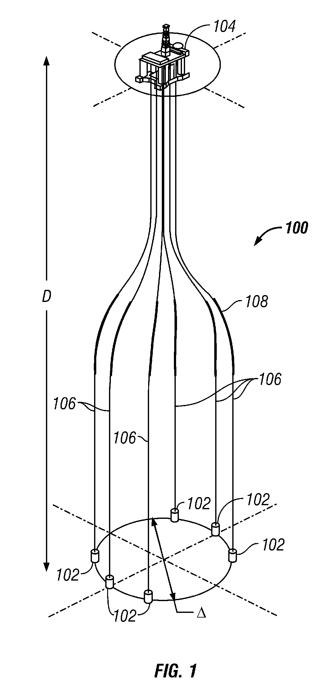
[0073]Referring initially to FIG. 1, a subsea well management system 100 is shown. Management system 100 can include a plurality of subsea wellheads 102 connected to a floating platform 104 through a plurality of variable tension risers 106. Subsea management system 100 can be designed and constructed to function in deepwater environments wherein the total water depth is greater than or equal to 300 meters (1,000 feet), but will have particular applicability at depths greater than or equal to 1220 meters (4,000 feet) up to 3050 or 4570 meters (10,000 or 15,000 feet), or more. Desirably, for the system 100 shown in FIG. 1, the water depth D between platform 104 and wellheads 102 should be between 1525 to 3050 meters (5,000 to 10,000 feet).

[0074]Variable tension risers 106 can be constructed as lengths of rigid pipe that become relatively compliant when extended over long lengths. For instance, while the materials of variable tension risers 106 may seem highly rigid at short lengths, ...


PUM


Abstract

Disclosed are compliant variable tension risers (106) to connect deep-water subsea wellheads (102) to a single floating platform (104) in wet tree or dry try systems. The variable tension risers (106) allow several subsea wellheads (102), in water depths from 1220 to 3050 meters, at lateral offsets from one-tenth to twice the depth or more, to tie back to a single floating platform (104). Also disclosed are methods to counter buoyancy and install variable tension risers using a weighted chain ballast line (228, 230).

Description

BACKGROUND OF THE INVENTION[0001]The present invention generally relates to the production of hydrocarbons from subsea wellheads located in deep to ultra-deep water depths. More particularly, the present invention relates to apparatuses and methods to produce hydrocarbons from a floating platform, supporting a dry tree connected to subsea wellheads located in deep water depths, and / or connected to a deep water wet tree at the subsea wellhead. More particularly still, the present invention relates to apparatuses and methods using compliant variable tension risers to hydraulically connect widely dispersed deep-water subsea wellheads to a floating platform.[0002]A variety of designs exist for the production of hydrocarbons in deep to ultra-deep waters, i.e. depths greater than 1220 meters (4,000 feet). Generally, the preexisting designs fall within one of two types, namely, wet tree or dry tree systems. These systems are primarily distinguished by the location of pressure and reservoir...

Claims


Application Information

Patent Timeline
Patent Type & Authority Patents(United States)
IPC IPC(8): E21B29/12
CPCB63B21/502E21B43/0107E21B17/012E21B43/017
Inventor BHAT, SHANKAR ULUVANAMUNGALL, JOHN CHRISTIAN HARTLEYANDERSEN, DAVID BRIANHAVERTY, KEVIN GERARDBARR, SEAN K.MANKU, DAVINDER
Owner KELLOGG BROWN & ROOT LLC
Learn More