Wireless linking of smoke/CO detection units

a detection unit and wireless technology, applied in the field of home alarms and detection units, can solve the problems of substantial hazard to those in the same house, inability to connect detection devices, and devices that provide no warning to those out of the hearing rang

Active Publication Date: 2008-08-26
BRK BRANDS +1
View PDF12 Cites 19 Cited by
  • Summary
  • Abstract
  • Description
  • Claims
  • Application Information

AI Technical Summary

Benefits of technology

[0013]The invention is a wireless environmental condition detector and event alarm system comprising a controller operable to enter a teaching mode when a test button communicably linked to said controller is actuated after battery power has already been engaged with the controller and when it receives a wirelessly transmitted learner address through a transceiver, to wirelessly transmit a learn-my-code command and teacher house code data (house code address) to the wirelessly transmitted learner address, through the transceiver. The controller is further operable to enter a learning mode when the test button is actuated and held during engagement of battery power, and further operable to wirelessly transmit through the transceiver a request teaching command and the learner address, and further operable to receive the learn-my-code command and the teacher house code data and electronically store said teacher house code data. This configuration allows the environment condition detector to link with other detectors configured with similar functionality.
[0019]In the case of the customer market, this invention provides lower cost solution and more secure method of creating a network by ensuring a random unique house code is generated when networking detectors together. Enhanced variations may include using multiple environment sensors and voice output.

Problems solved by technology

However, in the past, these detection devices were not interconnected.
Such devices however provide no warning to those out of the hearing range of the alarm sensing an alert condition.
This obviously creates a substantial hazard to those in the same house, building or other structure who are not informed of the dangerous condition.
Fire and the resulting smoke may unknowingly exist for significant periods of time in areas of buildings before the occupants are warned through conventional smoke detector systems where the detectors are not interconnected.
Even with a plurality of conventional smoke detectors, occupants in remote locations of a burning building may not be able to audibly detect the local alarm horn.
This results in a costly system and required the use of excessive wiring along floors, walls or ceilings.
Moreover, because each detection device typically generated sound at the detected location, the prior art devices were consumers of electrical power and were often unreliable and expensive.
Such wireless systems actually require, therefore, considerable wiring, which makes them expensive to install and requires skilled installers.
However, these systems are not usually installed by the average consumer.
Because of the control panel installation and wiring required, prior wireless alarm systems are unduly complicated, especially for a typical homeowner to install or service, and do not have the benefits of typical hardwired systems.
Accordingly, the potential of wireless home fire alarm systems has not been realized.
This method works fine in principle but has the drawbacks of layout issues, manually setting a random number at the factory or by the customer: cost of the switch, reliability of the switch in corrosion or manufacturing, number of unique ID's dependant on the number of switch positions and additional circuitry needed to decode the switch to cut down on number of I / O pins needed to read the switch by the microcontroller.
These attempts although eliminating the dip switch still require additional circuitry or the inflexibility of adding or removing alarms from the network.

Method used


Image

  • Wireless linking of smoke/CO detection units
  • Wireless linking of smoke/CO detection units
  • Wireless linking of smoke/CO detection units

Examples


Embodiment Construction

[0024]According to the embodiment(s) of the present invention, various views are illustrated in FIG. 1-5 and like reference numerals are being used consistently throughout to refer to like and corresponding parts of the invention for all of the various views and figures of the drawing. Also, please note that the first digit(s) of the reference number for a given item or part of the invention should correspond to the Fig. number in which the item or part is first identified.

[0025]One embodiment of the present invention comprising environmental condition detectors operable to link forming a network teaches a novel apparatus and method for networking smoke detectors and other environmental detectors.

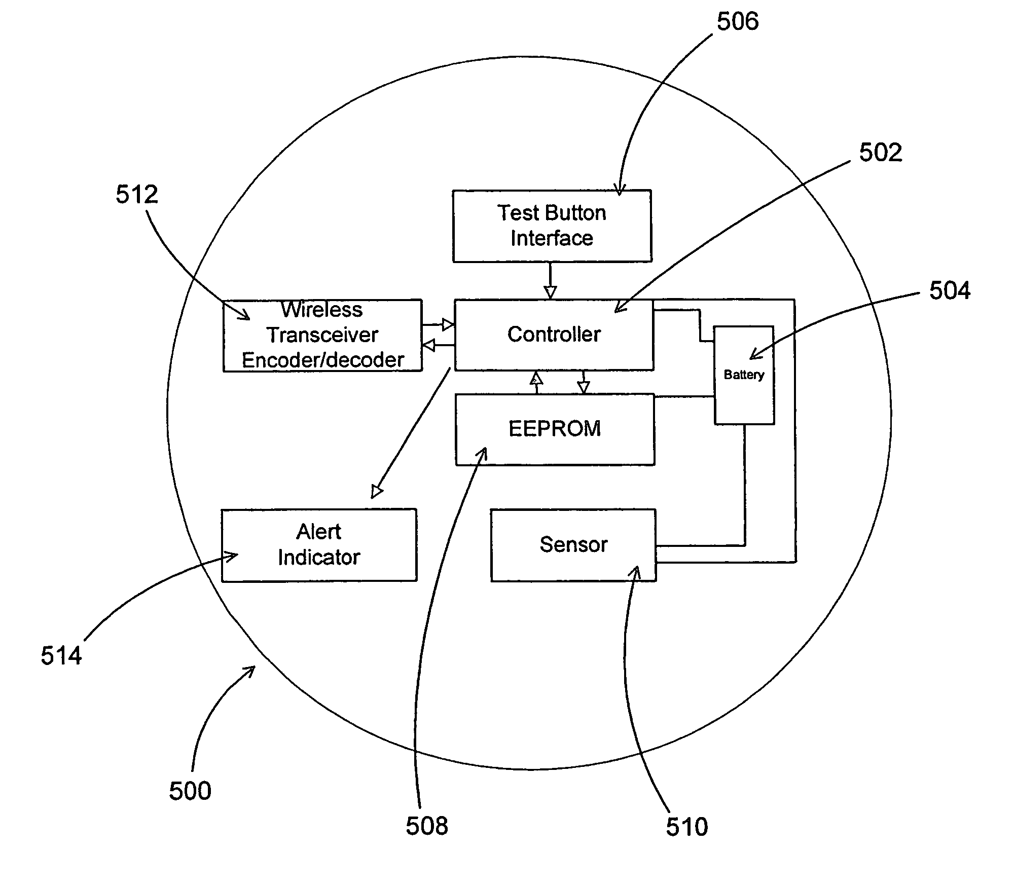
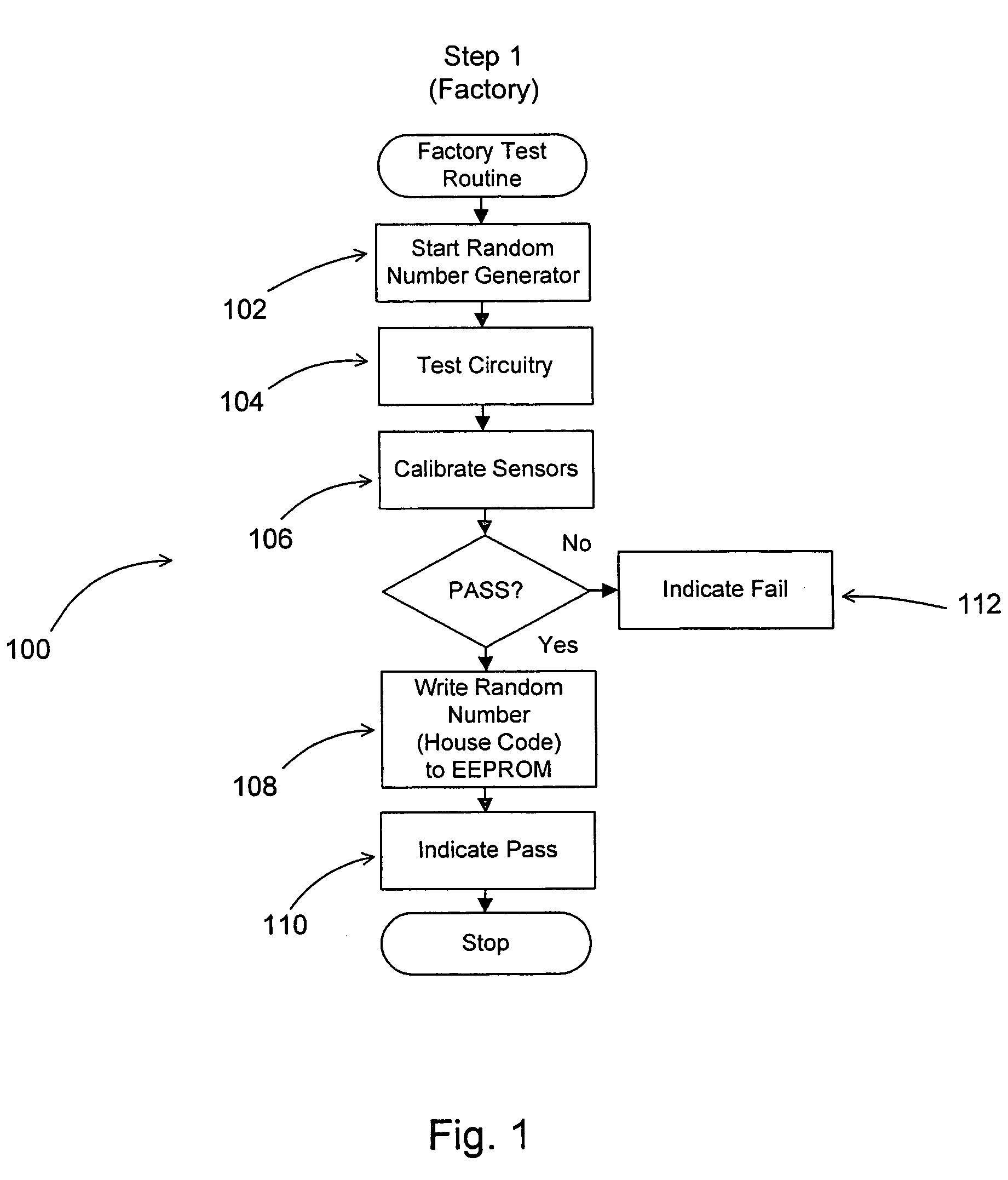
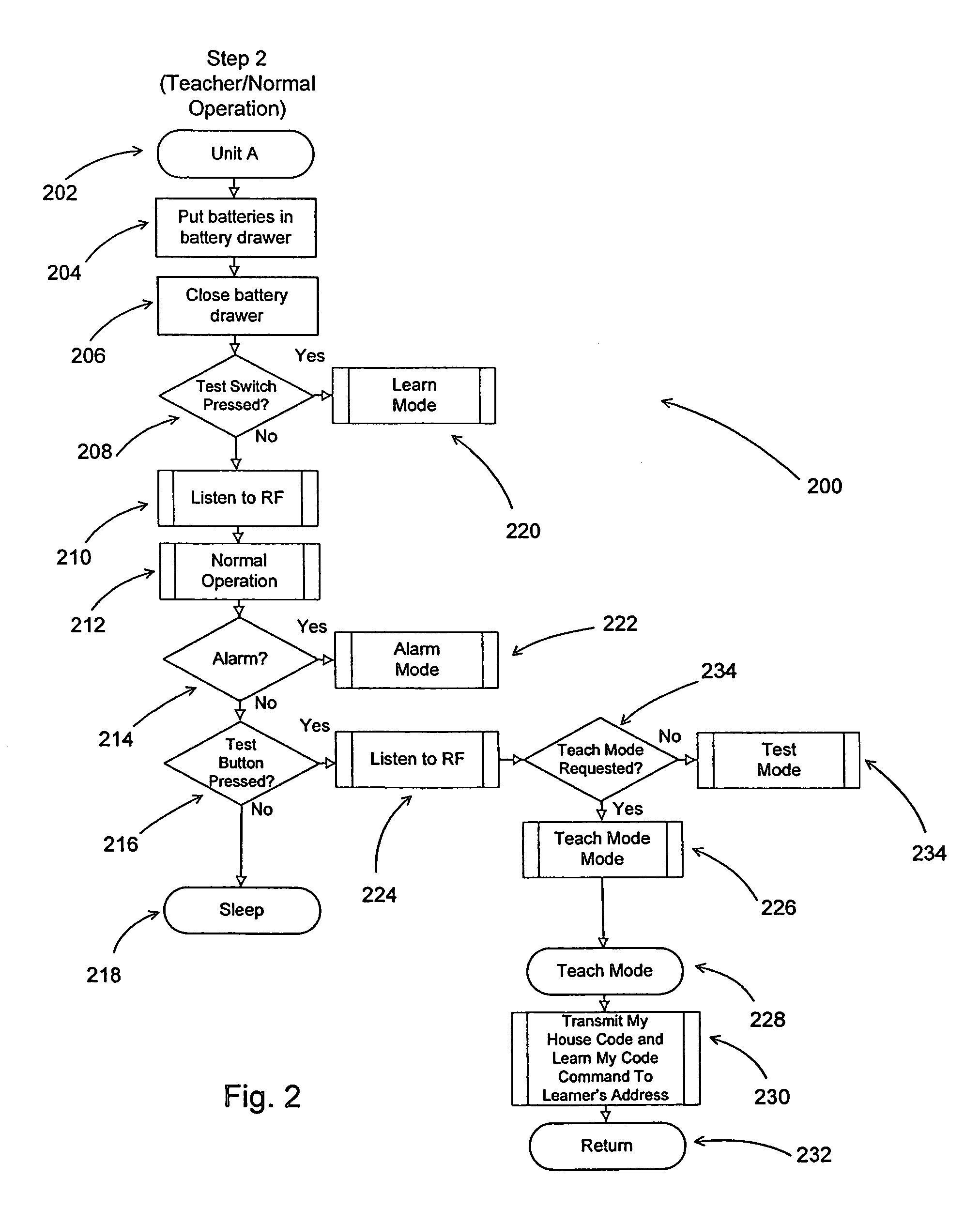
[0026]The details of the invention and various embodiments can be better understood by referring to the figures of the drawing. Referring to FIGS. 1-5, a functional diagram illustrating an environmental condition detector with some of the primary components is shown. The environmental condi...


PUM


Abstract

A wireless detector and alarm system, such as for example a smoke detector and / or carbon monoxide (CO) detector, operable to be linked and unlinked with one or more like detectors thereby forming a network of detectors. A detector sensing the presence of an environmental condition, which requires the sounding of an alert is operable to transmit a signal to other remotely linked detectors, thereby triggering the remotely linked detectors to sound an appropriate alarm. The detector at the location of the environmental condition causing the alarm and the remotely linked detector are capable to operate in teach and learn modes such that the address or “house codes” of the detectors can be synchronized.

Description

BACKGROUND OF INVENTION[0001]This invention relates generally to home alarm and detection units and, more particularly, to wireless linking of detection units.[0002]There are various types of smoke and Carbon Monoxide (CO) detecting devices that have been developed, such devices typically being battery powered, hardwired or wall-plug powered units designed to sound an alarm at the site of the detected smoke conditions. Smoke detection systems can include a plurality of detector units strategically positioned throughout the monitored area. Each of the plurality of detector units can include a detector for sensing one of a characteristic and condition within a section of the monitored area and generating a signal indicative of the monitored condition.[0003]A signal processor or controller can be connected within each detector unit for analyzing the signal generated by the detector and upon determining if the signal is above a predetermined level generating an emergency signal. A trans...

Claims


Application Information

Patent Timeline
Patent Type & Authority Patents(United States)
IPC IPC(8): G08B1/08
CPCG08B17/00G08B25/10G08B25/003
Inventor JOHNSTON, DEREKBROOKS, FLOYD
Owner BRK BRANDS
Why Eureka
Try Eureka