Single-sided inflatable vertical slit valve

a vertical slit valve, single-sided technology, applied in the direction of valve member-seat contact, mechanical equipment, coating, etc., can solve the problem of increasing the likelihood of particle generation in the system

Active Publication Date: 2008-09-09
APPLIED MATERIALS INC
View PDF54 Cites 379 Cited by
  • Summary
  • Abstract
  • Description
  • Claims
  • Application Information

AI Technical Summary

Problems solved by technology

The use of contact surfaces and multiple shaft support mechanisms results in additional friction areas that will increase the likelihood of particle generation in the system.

Method used


Image

  • Single-sided inflatable vertical slit valve
  • Single-sided inflatable vertical slit valve
  • Single-sided inflatable vertical slit valve

Examples


Embodiment Construction

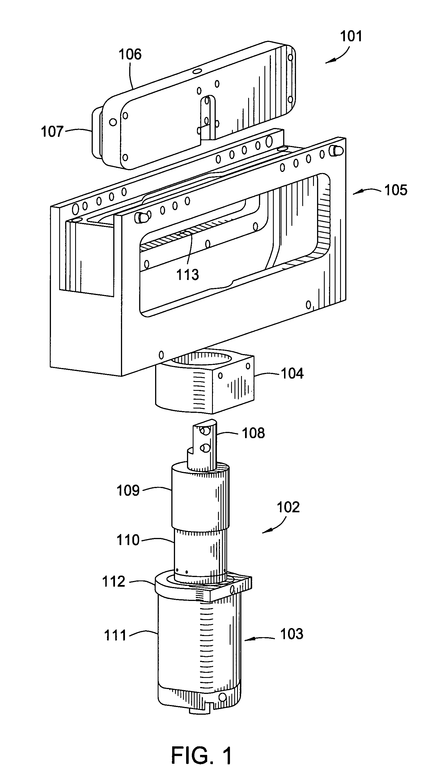
[0016]FIG. 1 is an exploded view of a gate valve assembly. The gate valve assembly consists of three major parts; a bellows head assembly 101, a shaft assembly 102, and a vertical actuator assembly 103. The gate valve assembly of FIG. 1 includes a mount block 104 that secures to a valve housing 105 that is part of a commercial vacuum chamber. The vertical actuator assembly 103, mount block 104, and valve housing 105 may have pinned connections. For example, the embodiment featured in FIG. 1 shows a valve housing 105 that may be incorporated into a Centura™ transfer chamber, available from Applied Materials, Inc.

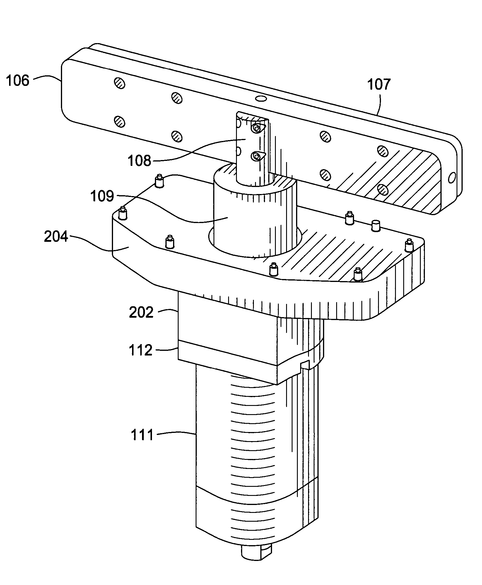
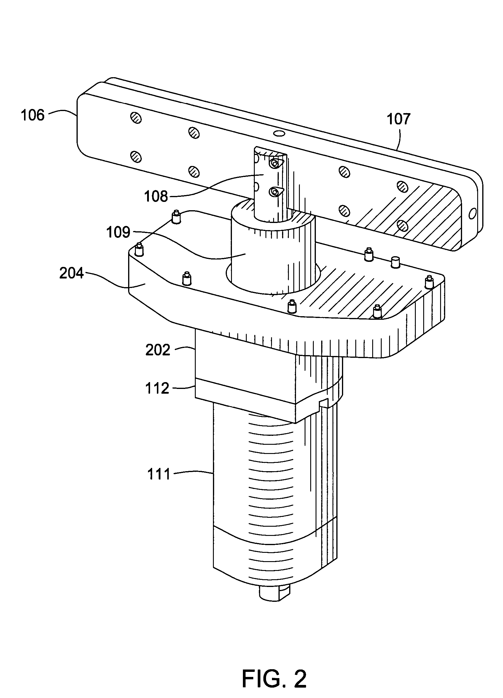
[0017]The bellows head assembly 101 includes a support block 106 and sealing door 107. The support block 106 is fastened to an end of a valve shaft 108 of the shaft assembly 102. The valve shaft 108 is fastened at the other end to a vertical actuator 111 as described for FIG. 3, and is covered during movement by exterior shaft cover 109 and interior shaft cover 110. The verti...


PUM

PropertyMeasurementUnit
vacuumaaaaaaaaaa
temperatureaaaaaaaaaa
pressureaaaaaaaaaa

Abstract

A vacuum chamber having a gate valve including a chamber housing defining an internal vacuum region and first and second openings through the chamber housing and a gate valve secured to the chamber housing. The gate valve includes a sealing door located in the processing region and configured to seal the first opening in the chamber housing; a vertical actuator located outside the chamber housing; a one-sided horizontal actuator located within the processing region and connected to the sealing door; and a valve shaft extending through the second opening in the chamber housing and connecting the vertical actuator to the one-sided horizontal actuator.

Description

BACKGROUND OF THE INVENTION[0001]1. Field of the Invention[0002]Embodiments of the present invention generally relate to gate valves for vacuum chambers, more specifically, slit valves for use in the semiconductor processing industry.[0003]2. Description of the Related Art[0004]Integrated process tools are often used in the semiconductor processing industry to rapidly expose a single substrate to many chemical and mechanical processes. These processes are performed in multiple chambers that are connected by additional transport, storage, and temperature and pressure adjustment chambers. To isolate the chambers during substrate processing, specialized gate valves are used. The gate valves are designed to operate in low pressure and harsh processing conditions and to provide enough of a transfer area to accommodate the substrate support robot or other mechanism that moves a substrate through slits in an integrated processing tool. Gate valves are often designed to reduce friction betw...

Claims


Application Information

Patent Timeline
Patent Type & Authority Patents(United States)
IPC IPC(8): C23C16/00C23F1/00F16K25/00F16K3/00H01L21/306
CPCH01L21/67126C23C16/54
Inventor BLAHNIK, JEFFKRAUS, JOERICE, MIKE
Owner APPLIED MATERIALS INC
Why Eureka
Try Eureka