Lens transfer device

a technology for transferring devices and lenses, applied in the direction of printers, instruments, cameras, etc., can solve the problems of large power consumption of electromagnetic motors of lens transfer devices, difficult miniaturization, and generation of electromagnetic waves harmful to human bodies, etc., and achieve the effect of simplifying the driving structure and small siz

Active Publication Date: 2008-09-16
SAMSUNG ELECTRO MECHANICS CO LTD
View PDF18 Cites 9 Cited by
  • Summary
  • Abstract
  • Description
  • Claims
  • Application Information

AI Technical Summary

Benefits of technology

[0022]The present invention has been made to solve the foregoing problems of the prior art and therefore an object of certain embodiments of the present invention is to provide a lens transfer device which can have a micro size owing to a simplified driving structure over a conventional electromagnetic driving mechanism.
[0023]Another object of the invention is to provide a lens transfer device capable of producing a large displacement from a low input supply voltage, thereby achieving excellent transfer resolution and minimizing power loss in relation with the operation of the device.
[0024]Further another object of the invention is to provide a lens transfer device having a guide mechanism for the transfer of a lens simplified over the prior art, capable of transferring a lens more precisely and stably.
[0038]More preferably, the first and second guide rods are coated on outer peripheries with one material of fluorocarbons and molybdenum sulfides to minimize frictional force.

Problems solved by technology

Since the lens transfer device as above has a plurality of deceleration gears, it is difficult to miniaturize it.
Furthermore, the electromagnetic motor of the lens transfer device consume a large amount of power and generates electromagnetic waves harmful to the human body as well.
In addition, it is difficult to transfer the lens with high precision.
However, the zoom lens mechanism of this camera also uses an electromagnetic motor and thus needs a plurality of deceleration gears, which in turn hinders miniaturization.
Furthermore, it is difficult to clear electromagnetic waves generating from the motor or to transfer the lens with high precision.
However, the driving rod 36 is fixed in length and thus the length of the barrel is not adjustable, which makes it difficult to miniaturize the device.

Method used


Image

  • Lens transfer device
  • Lens transfer device
  • Lens transfer device

Examples


Embodiment Construction

[0055]The present invention will now be described more fully hereinafter with reference to the accompanying drawings, in which preferred embodiments of the invention are shown.

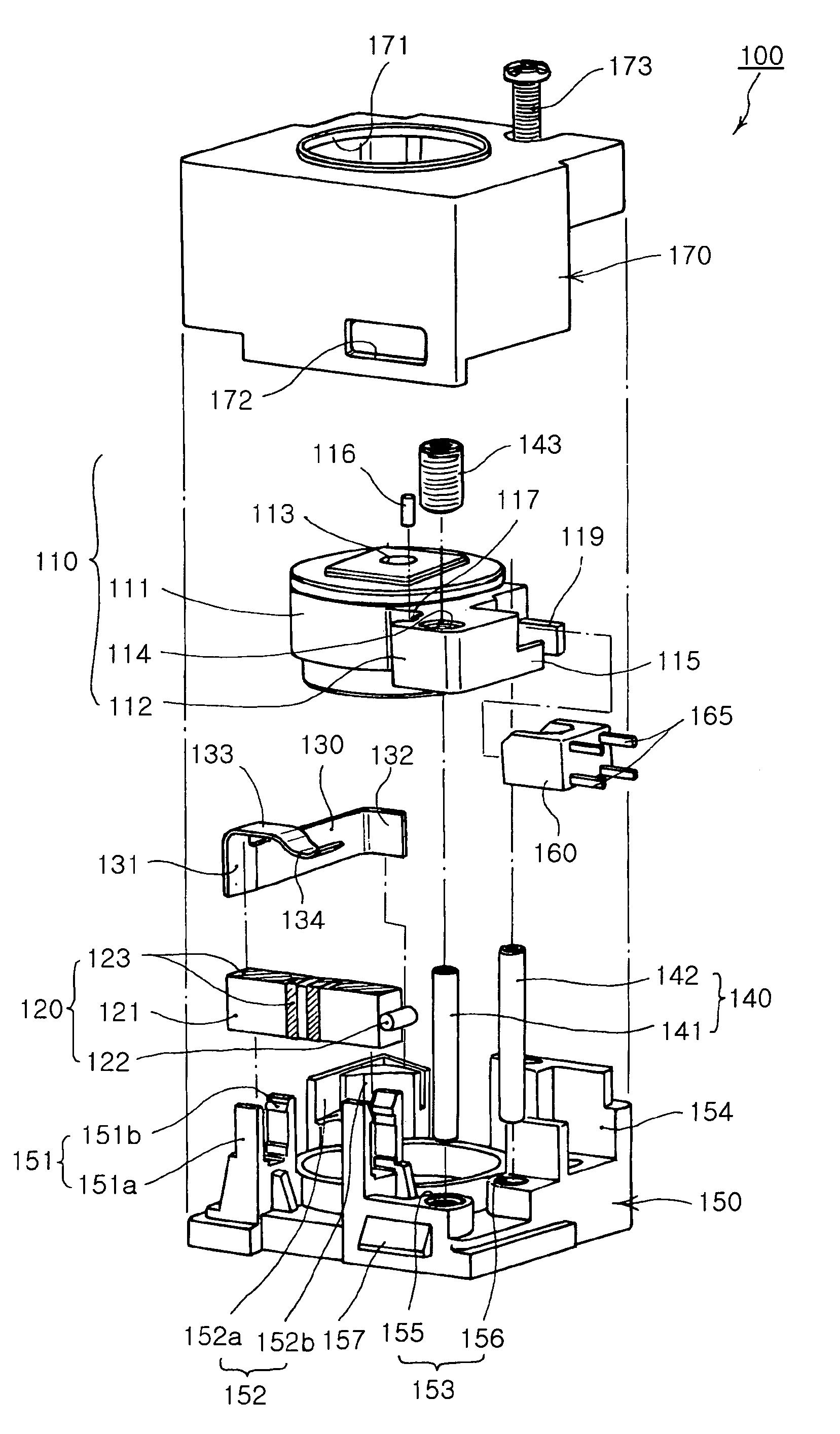
[0056]FIG. 4 is a perspective view illustrating a lens transfer device 100 according to the invention, and FIG. 5 is an exploded perspective view illustrating the lens transfer device 100 as shown in FIG. 4.

[0057]Referring to FIGS. 4 and 5, the lens transfer device 100 of the invention includes a lens barrel 110 with at least one lens contained therein, an actuator 120 for supplying a driving force to transfer the lens, a pressing member 130 for pressing the actuator 120 and a guide 140 for guiding the transfer of the lens barrel 110.

[0058]The lens barrel 110 includes a lens receiving part 111 and an extension 112. The lens receiving part 111 is of a container having a predetermined size of inner space which receives at least one lens to be oriented along the optical axis. The extension 112 is of a substantial...


PUM


Abstract

The invention provides a lens transfer device including at least one lens and a lens barrel. The lens barrel has a lens receiving part with the lens arranged in an inner space thereof and an extension extending radially from an outer surface of the lens receiving part. An actuator has a body and an output member at a leading end of the actuator to contact the extension, and is adapted to expand / contract and bend in response to an external supply voltage to provide a driving force necessary for transfer of the lens barrel through the output member. A pressing member has a free end contacting a rear end of the actuator to force the actuator against the extension, and a guide guides the transfer of the lens barrel along an optical axis.

Description

CLAIM OF PRIORITY[0001]This application claims the benefit of Korean Patent Application No. 2005-100199 filed on Oct. 24, 2005, in the Korean Intellectual Property Office, the disclosure of which is incorporated herein by reference.BACKGROUND OF THE INVENTION[0002]1. Field of the Invention[0003]The present invention relates to a device for transferring a lens in use for an optical device, and more particularly, a lens transfer device with a simple structure of drive mechanism, by which a miniaturization design can be enabled, power loss related with lens transfer can be minimized and a lens can be transferred more precisely and stably.[0004]2. Description of the Related Art[0005]In general, an optical instrument has a lens transfer device for transferring a lens by using a cam, screw, motor or piezoelectric element. The lens transfer device uses the motor or piezoelectric element as means for generating driving force and the cam or screw for delivering the driving force.[0006]Accord...

Claims


Application Information

Patent Timeline
Patent Type & Authority Patents(United States)
IPC IPC(8): G02B15/14G02B27/00
CPCG02B7/102G02B7/04H10N30/50G02B7/022G03B3/10H02N2/0055H02N2/02G03B2205/0069
Inventor PAIK, KI MUNBIN, YOUN KYUNLEE, JUNG SEOKLEE, DONG KYUNKANG, BYUNG WOORYU, JUNG HOKIM, SUNG DEUKKOC, BURHANETTIN
Owner SAMSUNG ELECTRO MECHANICS CO LTD
Why Eureka
Try Eureka