Lighting device for display device, display device and television receiver

a technology for display devices and television receivers, which is applied in the direction of static indicating devices, lighting and heating devices, instruments, etc., can solve the problems of unlikely failure of wiring or mounting, and achieve the effect of reducing costs, simplifying parallel drive structures, and reducing failures

Inactive Publication Date: 2009-11-10
SHARP KK
View PDF22 Cites 9 Cited by
  • Summary
  • Abstract
  • Description
  • Claims
  • Application Information

AI Technical Summary

Benefits of technology

[0007]In order to overcome the problems described above, preferred embodiments of the present invention enable parallel drive for light sources by a simplified parallel drive structure so as to contribute to large cost reduction, and thereby provide a failure-resistant and highly-reliable lighting device for a display device. In addition, preferred embodiments of the present invention provide a display device having the lighting device for a display device, and provide a television receiver having the display device.

Problems solved by technology

Further, wiring or mounting-related failures are unlikely to occur, which could result in a highly-reliable lighting device for a display device.

Method used


Image

  • Lighting device for display device, display device and television receiver
  • Lighting device for display device, display device and television receiver
  • Lighting device for display device, display device and television receiver

Examples


Embodiment Construction

[0061]Hereinafter, preferred embodiments of the present invention will be explained with reference to the drawings.

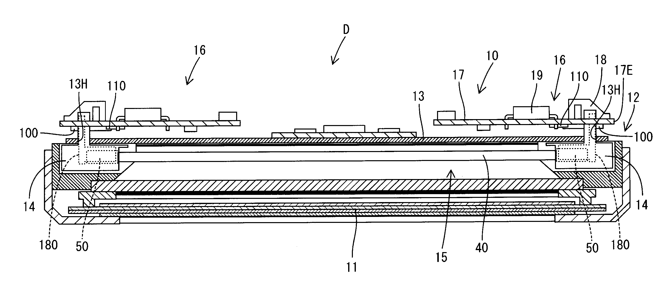
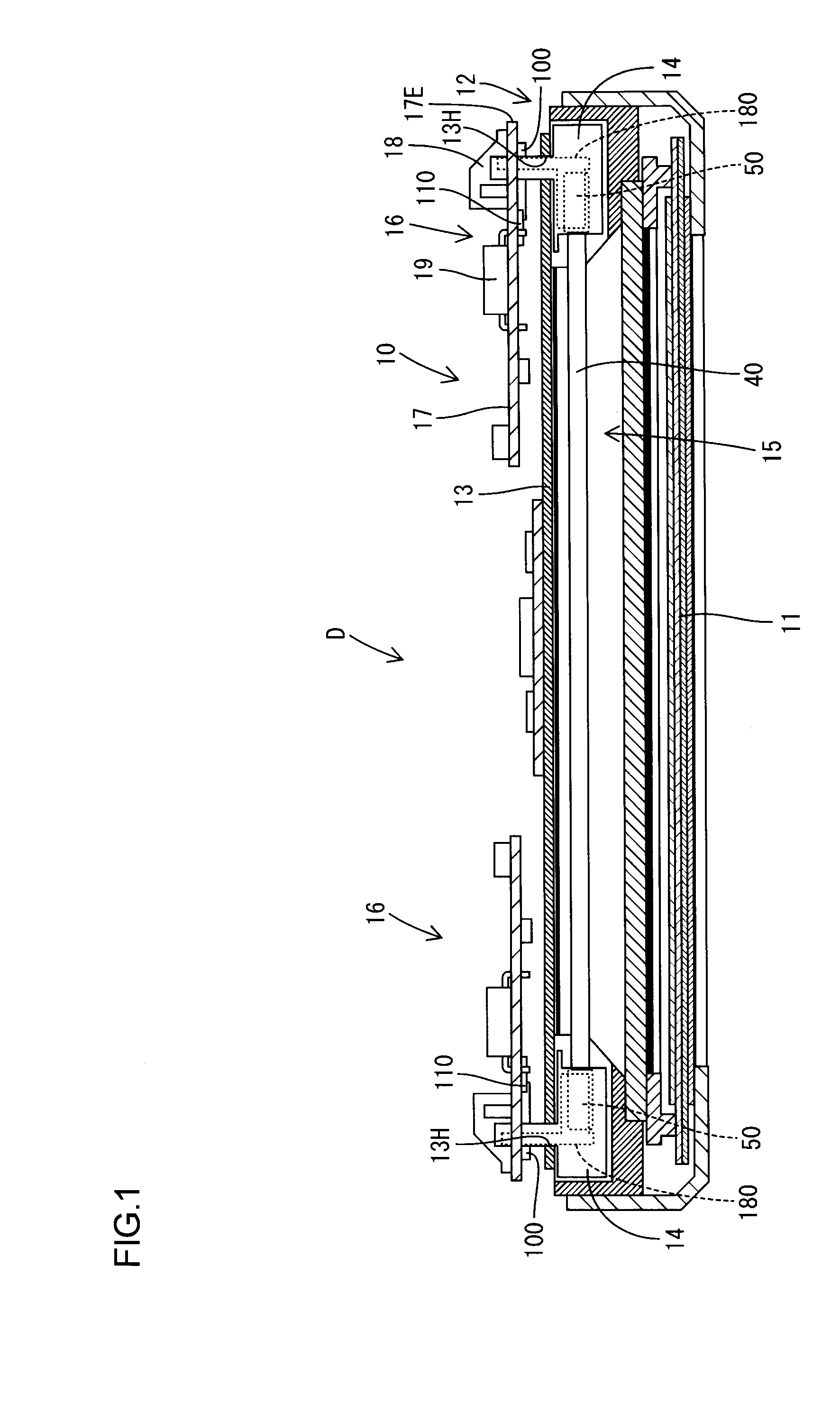
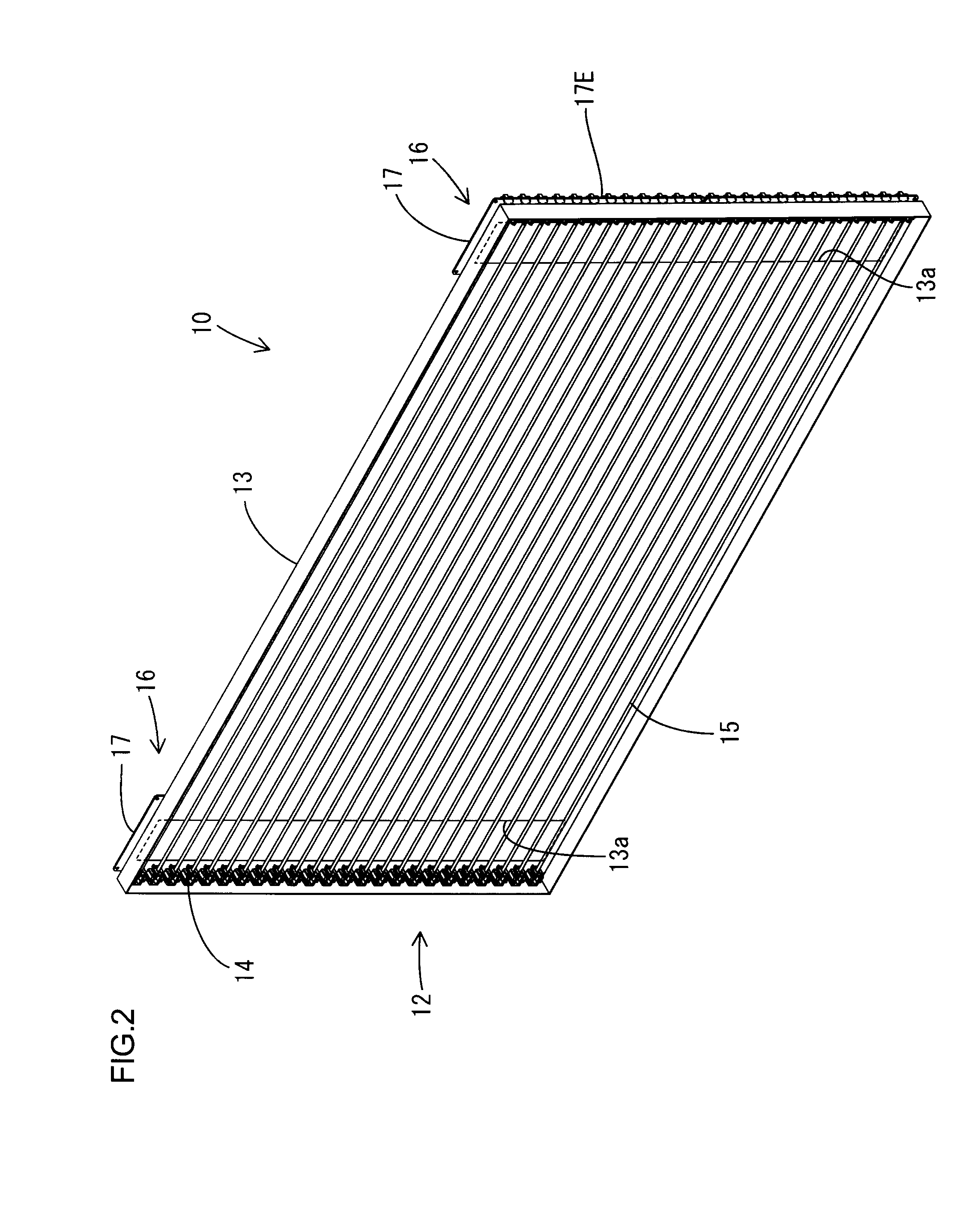
[0062]FIG. 1 is a horizontal sectional view of a liquid crystal display device (a display device) D of the present preferred embodiment. FIG. 2 is a perspective view of a lighting device (a lighting device for a display device) 10 included in the liquid crystal display device D. FIG. 3 is a rear elevational view of the lighting device 10. FIG. 4 is a perspective view of a power board (a circuit board) 16 included in the lighting device 10. FIG. 5 is a front elevational view of the power board 16. FIG. 6 is a perspective view of a discharge tube 15. FIG. 7 is an explanatory diagram schematically showing a drive power supply structure for discharge tubes 15.

[0063]FIG. 8 is an explanatory diagram schematically showing a modification of the drive power supply structure for discharge tubes 15. FIG. 9 is a schematic diagram separately showing the construction of the supply st...


PUM


Abstract

A lighting device for a display device includes a plurality of light sources, a power source arranged to provide drive power for the light sources, a common electrode arranged to supply the drive power to the plurality of light sources, a plurality of holder electrodes arranged to hold the respective light sources and supply the drive power from the common electrode individually to the respective light sources, and a dielectric portion provided between the common electrode and each of the holder electrodes.

Description

CROSS REFERENCE TO RELATED APPLICATION[0001]The present application is a continuation of International Application No. PCT / JP2007 / 070057 filed Oct. 15, 2007, which claims priority from Japanese Patent Application No. 2007-035192 filed Feb. 15, 2007. The entire contents of both applications are incorporated herein by reference.BACKGROUND OF THE INVENTION[0002]1. Field of the Invention[0003]The present invention relates to a lighting device for a display device, a display device and a television receiver.[0004]2. Description of the Related Art[0005]In a display device having non-luminous optical elements as typified by a liquid crystal display device, a backlight device is provided on the backside of a display panel such as a liquid crystal panel, so as to illuminate the display panel (as shown in JP-A-2006-245005, for example).[0006]The backlight device, disclosed in JP-A-2006-245005, has a structure that enables parallel drive for CCFLs. That is, a lamp drive device is disclosed in ...

Claims


Application Information

Patent Timeline
Patent Type & Authority Patents(United States)
IPC IPC(8): H05B37/00F21V23/00F21Y101/00
CPCG02F1/133604H01J5/50H01J65/046H01J61/305H01J5/54G02F2001/133612H01J61/56G02F1/133612F21V19/0085G02F1/1345G02F1/133G02F1/1343
Inventor TAKATA, YOSHIKI
Owner SHARP KK
Why Eureka
Try Eureka