Electrical connector assembly having improved pickup cap

a technology of electric connectors and parts, applied in the direction of electrical connectors, heating types, lighting and heating apparatus, etc., can solve the problems of destroying the hooks of the pick up cap and the parts of the electrical connector, and achieve the effect of reducing the force used for assembly

Active Publication Date: 2008-09-30
HON HAI PRECISION IND CO LTD
View PDF3 Cites 10 Cited by
  • Summary
  • Abstract
  • Description
  • Claims
  • Application Information

AI Technical Summary

Benefits of technology

[0008]Accordingly, an object of the present invention is to provide an electrical connector assembly, which has an electrical connector and a pick up cap mounted onto the connector, wherein the pick up cap is configured to facilitate detachment of the pick up cap from the connector and ensure a stably and reliably connection between the pick up and the electrical connector.
[0010]Relative to the present technology, the pick up is mounted on the electrical connector by an elastic engagement. As a result, when assembled or disassembled, the force used for assembly can decrease, hence the hooks of the pick up are not prone to be destroyed and the electrical connection between the terminals and the leads of the chip module is more stable than ever.

Problems solved by technology

When the electrical connector assembly is assembled or disassembled, the force applied on the pick up cap and the electrical connector has to be greater than ever, which is prone to destroy the hooks of the pick up cap and the parts of the electrical connector.
In addition, the greater shake during the assembling the pick up cap on the electrical connector can make an open electrical connection and a fail mechanical connection between terminals and leads of the chip module.

Method used


Image

  • Electrical connector assembly having improved pickup cap
  • Electrical connector assembly having improved pickup cap
  • Electrical connector assembly having improved pickup cap

Examples


Embodiment Construction

[0018]Reference will now be made to the drawings to describe the present invention in detail.

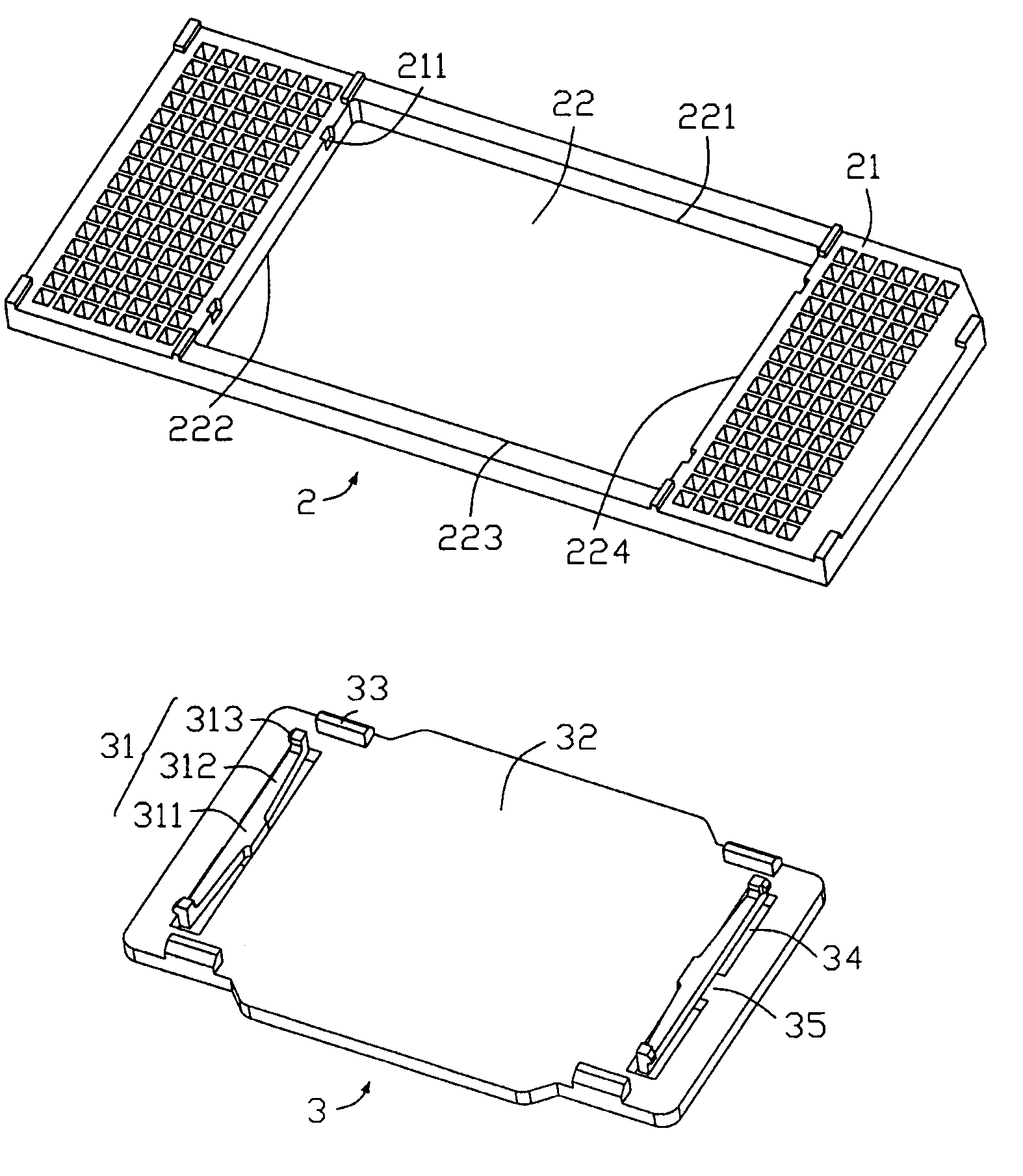
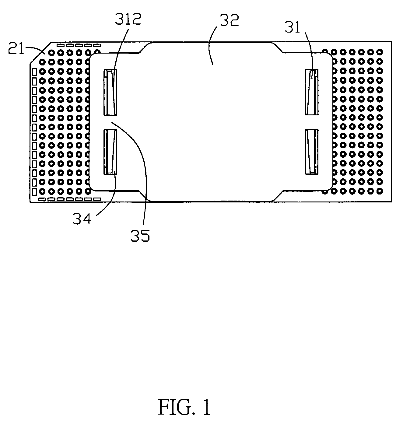
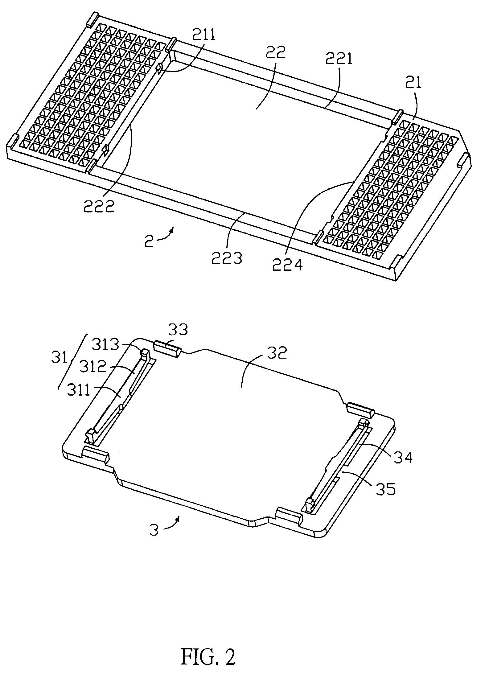
[0019]Referring to FIG. 1, an electrical connector assembly in accordance with a preferred embodiment of the present invention comprises an electrical connector 2 and a pick up cap 3 mounted onto the connector 2, for providing a plane top surface to be engaged by a vacuum suction device. The connector assembly can thereby be moved onto a circuit substrate, such as a printed circuit board (PCB) (not shown), on which the connector 2 is to be mounted.

[0020]The electrical connector 2 comprises a housing 21 and a plurality of terminals received in the housing 21. The housing 21 is rectangular-shaped and comprises a rectangular opening 22 in a central portion thereof and a plurality of passageways for receiving the terminals therein and a first lateral side 221, a second lateral side 222, a third lateral side 223 and a fourth lateral side 224 defined around the opening 22. The second lateral side ...


PUM


Abstract

An electrical connector assembly comprises an electrical connector (2), a pick up cap (3) for engaging with the electrical connector (2). The electrical connector (2) comprises a housing (21), a plurality of terminals received in the housing (21). The housing (21) defines an opening (22) in a central position thereof and a pair of securing recesses (211) on two lateral sides of the housing (2) adjacent to the opening (22). The pick up cap (3) defines a smooth vacuum suction portion (32) in a central position thereof and a pair of rectangular holes (34) arranged on two sides of the vacuum suction portion (32), a pair of beams (35) disposed on sidewalls of the base portion adjacent to the holes (34). The beam (35) extends downwardly a pair of elastic hooks (31). The elastic hooks (31) engage with the securing recesses (211) of the base portion respectively.

Description

BACKGROUND OF THE INVENTION[0001]The present invention claims the foreign priority of TW patent application Serial No. 95106506, filed on Feb. 27, 2006, which have the same applicant and assignee as the present invention.[0002]1. Field of the Invention[0003]The present invention relates to the art of an electrical connector assembly having a pick up cap, and more particularly to an electrical connector assembly provided for electrically connecting a chip module to a printed circuit board (PCB).[0004]2. Description of the Prior Art[0005]Referring to FIG. 5-6, an electrical connector assembly is widely used in the connector industry for electrically connecting a chip module to a printed circuit board (PCB) in personal computer comprises an electrical connector 2′ and a pick up 3′. The pick up cap 3′ is mounted onto the connector 2′ for providing a plane surface to be engaged by a vacuum suction device. The electrical connector 2′ comprises a housing 21′ received a plurality of termina...

Claims


Application Information

Patent Timeline
Patent Type & Authority Patents(United States)
IPC IPC(8): H01R13/44
CPCH05K7/1007F24F13/32
Inventor LIAO, FANG-JWU
Owner HON HAI PRECISION IND CO LTD
Why Eureka
Try Eureka