
Bicycle having annular sealing member

a sealing member and bicycle technology, applied in the field of bicycle rims, can solve the problems of reducing sealing effectiveness, affecting wheel performance, and prior designs suffering from deficiencies, so as to minimize wear and/or damage to the seal structure, and tight seal without compromising wheel performance

Inactive Publication Date: 2008-10-07
SHIMANO INC
View PDF44 Cites 17 Cited by
  • Summary
  • Abstract
  • Description
  • Claims
  • Application Information

AI Technical Summary

Benefits of technology

The solution provides a durable, lightweight, and cost-effective sealing structure that maintains optimal tire performance by minimizing seal damage and wear, even after repeated installations, while being easy to manufacture and assemble.

Problems solved by technology

While the use of a seal at the outer portion of the rim generally works well, the prior designs suffer from deficiencies.
Also, with some designs, the seal may work very well initially but the sealing effectiveness can be reduced, especially after prolonged use.
The tire itself and the tire levers can cause damage or wear to the seal during such replacement of the tire.
Removal and reinstallation of the tire and / or seal can cause the seal and / or tire to be stretched, worn and / or damaged.
Even if the seal and tire are not removed, normal riding can also cause wear to some of these prior seals.
These ribs can become worn and / or damaged due to repeated small movements of the tire beads during riding.
In any case, if these ribs become worn or damaged, performance of the tire may not be optimal.
In other words, with these prior rim and seal designs the sealing effectiveness is not always optimal, especially after prolonged normal use and / or repeated removal and reattachment of the tire and / or seal.
Also, with these prior rims, even if the sealing effectiveness is maintained after prolonged use, tire performance can be adversely affected due to wear or damage to the seal.
Whiles these types of prior rims generally work well, these prior rims for tubeless tires suffer from other deficiencies.
Specifically, these rims can be relatively expensive, inconvenient and complicated to manufacture and assemble.
Also, these prior rims can be heavier than desired by some riders.
More specifically, these prior rims often require a non-traditional spoke mounting structure at the rim, which contributes to the relative cost, complexity, weight, etc. of these types of rims.

Method used


Image

  • Bicycle having annular sealing member
  • Bicycle having annular sealing member
  • Bicycle having annular sealing member

Examples


second embodiment

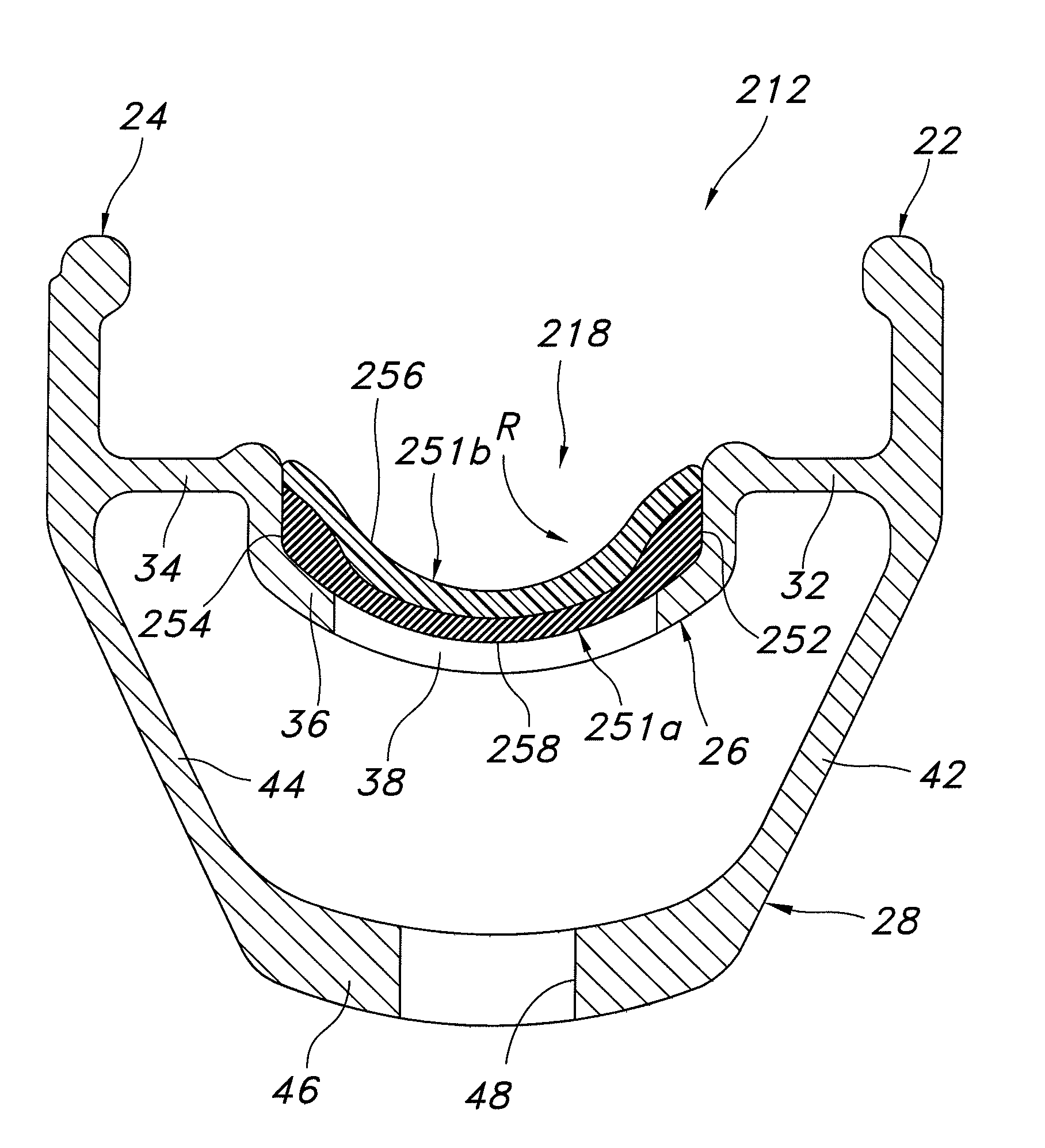
[0055]Referring now to FIG. 7, an annular bicycle rim 212 with a modified annular seal member 218 in accordance with a second embodiment will now be explained. The rim 212 of this second embodiment is identical to the rim 12 of the first embodiment, except the rim 212 has the modified seal member 218 mounted thereto. The seal member 218 is a modified version of the seal member 18 of the first embodiment. Specifically, the seal member 218 of this second embodiment is constructed of two different materials (e.g. layers) in this second embodiment. In view of the similarity between the first and second embodiments, the parts of the second embodiment that are identical to the parts of the first embodiment will be given the same reference numerals as the parts of the first embodiment. Moreover, the descriptions of the parts of the second embodiment that are identical to the parts of the first embodiment may be omitted for the sake of brevity. On the other hand, parts of this second embodi...

third embodiment

[0060]Referring now to FIG. 8, a modified annular bicycle rim 312 with a modified annular seal member 318 in accordance with a third embodiment will now be explained. The rim 312 of this third embodiment is identical to the rim 12 of the first embodiment, except the modified rim 312 has the modified outer annular bridge portion 326 with a modified seal member 318 mounted thereto. Specifically, the outer bridge portion 326 and the modified seal member 318 are configured and arranged to normally prevent outward radial movement of the seal member 318 relative to the outer bridge portion 326 once the seal member 318 is installed. In view of the similarity between the first and third embodiments, the parts of the third embodiment that are identical to the parts of the first embodiment will be given the same reference numerals as the parts of the first embodiment. Moreover, the descriptions of the parts of the third embodiment that are identical to the parts of the first embodiment may be...

fourth embodiment

[0062]Referring now to FIG. 9, a modified annular bicycle rim 412 with a modified annular seal member 418 in accordance with a fourth embodiment will now be explained. The rim 412 of this fourth embodiment is identical to the rim 12 of the first embodiment, except the modified rim 412 has the modified outer annular bridge portion 426 with a modified seal member 418 mounted thereto. Specifically, the outer bridge portion 426 and the modified seal member 418 are configured and arranged to normally prevent outward radial movement of the seal member 418 relative to the outer bridge portion 426 once the seal member 418 is installed. In view of the similarity between the first and fourth embodiments, the parts of the fourth embodiment that are identical to the parts of the first embodiment will be given the same reference numerals as the parts of the first embodiment. Moreover, the descriptions of the parts of the fourth embodiment that are identical to the parts of the first embodiment m...


PUM


Abstract

A bicycle rim includes first and second annular side portions, an annular bridge portion and an annular seal member. The bridge portion extends between the first and second side portions. The bridge portion includes first and second annular tire support surfaces and a recessed center surface. The recessed center surface is arranged between the first and second tire support surfaces to form an annular recess. The recessed center surface has a plurality of circumferentially arranged openings formed therein. The annular seal member is arranged in the annular recess to seal the openings.

Description

BACKGROUND OF THE INVENTION[0001]1. Field of the Invention[0002]This invention generally relates to a bicycle rim. More specifically, the present invention relates to a bicycle rim having a seal structure facilitating use with a tubeless tire.[0003]2. Background Information[0004]Bicycling is becoming an increasingly more popular form of recreation as well as a means of transportation. Moreover, bicycling has become a very popular competitive sport for both amateurs and professionals. Whether the bicycle is used for recreation, transportation or competition, the bicycle industry is constantly improving the various components of the bicycle. One component that has been extensively redesigned is the bicycle wheel. Bicycle wheels are constantly being redesigned to be lightweight and more aerodynamic in design as well as to be simple to manufacture and assemble.[0005]There are many different types of bicycle wheels, which are currently available on the market. Most bicycle wheels have a ...

Claims


Application Information

Patent Timeline
Patent Type & Authority Patents(United States)
IPC IPC(8): B60C15/02B60B21/00
CPCB60B1/041B60B1/044B60B21/025B60B21/026B60B21/04B60B21/062
Inventor SENOO, NORIHISA
Owner SHIMANO INC
Learn More