Sensor mount

a technology of sensor and mounting plate, applied in the direction of instruments, electromagnetic radiation sensing, mechanical measuring arrangement, etc., can solve the problems of preventing the free flow of packages, wasting considerable time and extra cost, and the type of design failing to anticipate the impact and rigor of long distances, speed, routing and other issues, to achieve the effect of minimizing wear or damage to either system, easy installation and adjustmen

Active Publication Date: 2020-12-22
BUNTAIN MARK
View PDF8 Cites 0 Cited by
  • Summary
  • Abstract
  • Description
  • Claims
  • Application Information

AI Technical Summary

Benefits of technology

[0008]It is an object of the invention to provide an economical accommodation to a multitude of devices which Is easy to install, easy to adjust and does not require painting or subsequent surface cleaning or treatment, can be manufactured of different materials, can be manufactured in different colors of material and can be designed w

Problems solved by technology

This is particularly the case for package transport conveyors, as they require obstruction-free paths, so that packages do not get restrained by anything protruding into the package path, which can create a jammed condition preventing free flow of packages.
The current standard practice is to expend considerable time and

Method used


Image

  • Sensor mount
  • Sensor mount
  • Sensor mount

Examples


Embodiment Construction

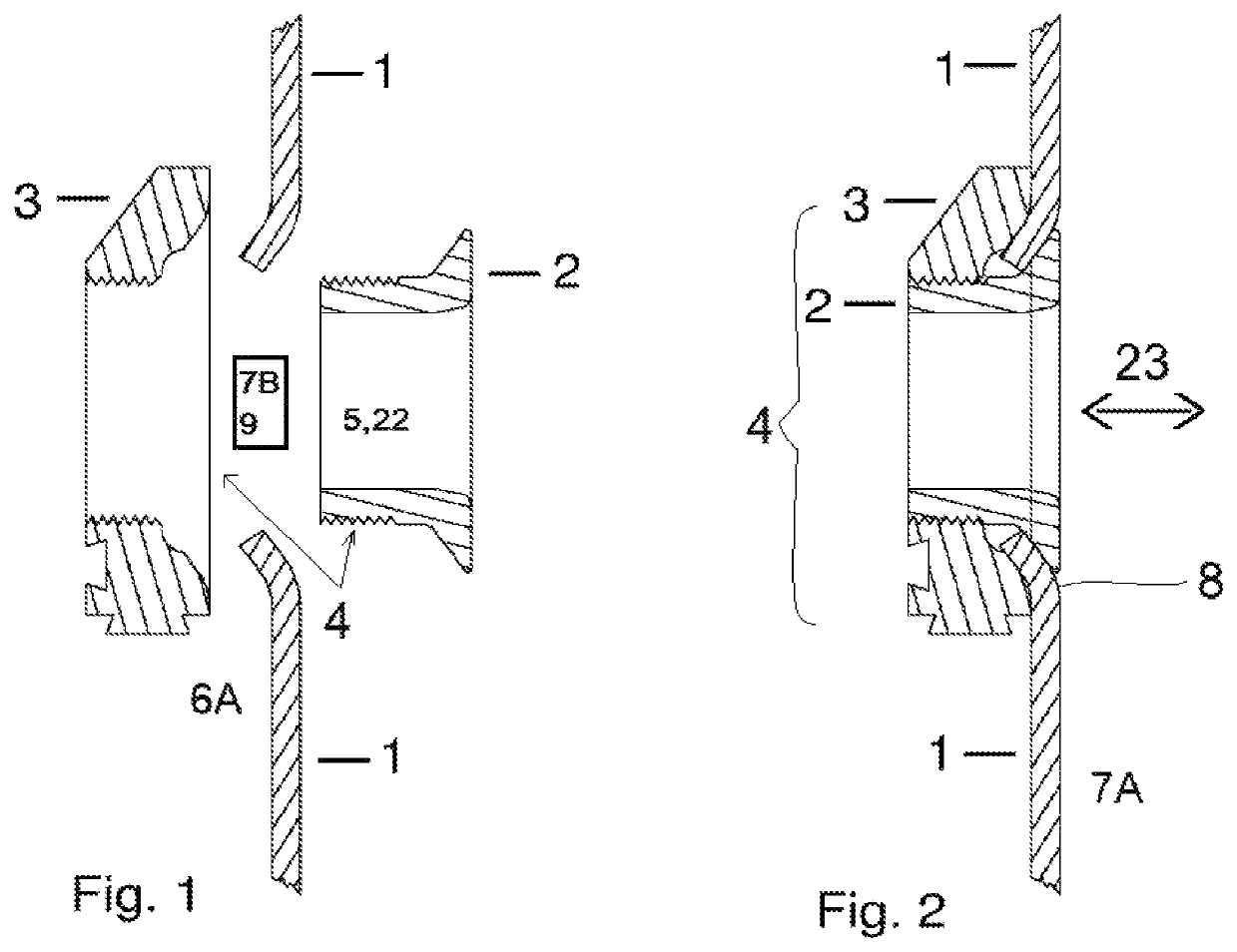
[0023]Referring to FIGS. 1 & 2, a key feature of major embodiments of the apparatus is the tapered surfaces of the primary element 2 and receiving element 3, as further described below in connection with FIG. 4. Side guard 1 is also shown, having a deformation corresponding to these tapered surfaces. A fundamental distinguishing aspect of the invention is the creation of the taper / conic / frusto-conic surface by deformation of the mounting substrate. This also creates two mounting surfaces 8: the one that primary element 2 (internal one) interfaces with and the one that receiving element 3 (external part) interfaces with. Also, surfaces 8 are created by deformation, not metal-cutting / removal. FIG. 2 shows the assembled configuration 4 of elements 2 and 3 on either side of the side guard 1.

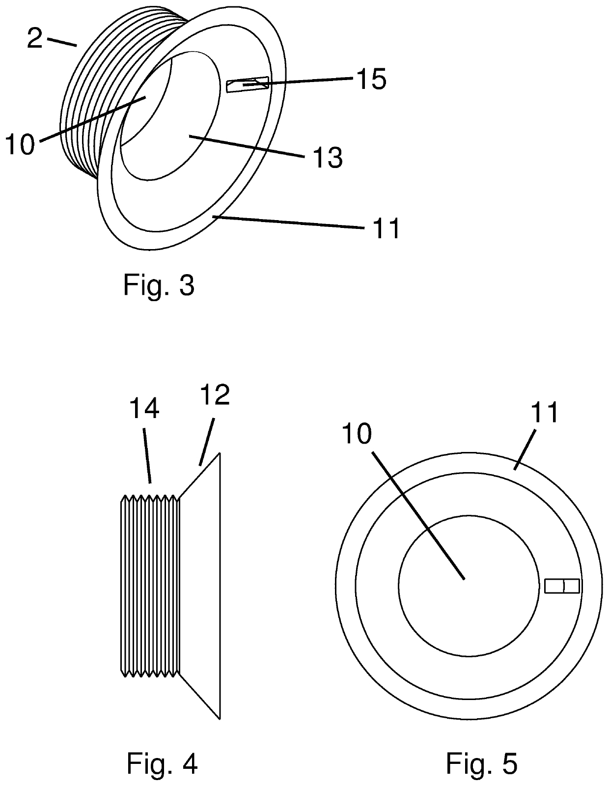
[0024]Referring to FIG. 3, in an embodiment, the primary element 2 contains a quantity of sub-surface indentations 15 to allow a mating tightening tool to interface with the device and be tightened i...


PUM


Abstract

The present invention pertains to the art of sensing articles typically moving on a conveyor. An apparatus is disclosed, for the purpose of securely attaching a sensing device to a sub-structure such as a sidepan metal sheet that contains a hole through which the sensing/detection device passes its sensing beam. A primary novelty of the apparatus is that it enables secure mounting of various ‘through-hole’ devices without the need for attaching any additional bracketry and without creating obstructions to package movement. It is unique in that it utilizes the “through-hole” which is necessary to allow passage of the sensing beam through the side guards of the conveyor, with the below-surface attachment being made possible by means of a tapered, or ‘sloping’ surface that is created when the hole is made.

Description

BACKGROUND OF THE INVENTION[0001]Sensor mounts are typically designed to be universal with little consideration for any unique needs or constraints of specific applications or industries. This is particularly the case for package transport conveyors, as they require obstruction-free paths, so that packages do not get restrained by anything protruding into the package path, which can create a jammed condition preventing free flow of packages.[0002]The current standard practice is to expend considerable time and extra cost to acquire, cut and prepare the components to attach brackets and devices that allow the sensors to be located in the proper orientation and function properly. These are typically metal components that need to be cut from longer standard lengths of a “Uni-Strut-type” member, deburred of sharp edges, welded to the side of the conveyor, de-slagged to remove welding residue, surface prepped to provide a good painting surface for primer and additional top coats of finis...

Claims


Application Information

Patent Timeline
IPC IPC(8): G01D11/24G01B5/00G06K7/10
CPCG06K7/10792G01D11/245G01B5/0004G06K7/10722B65G21/2072B65G43/08B65G2203/041B65G2203/042B65G2203/044B65G2203/047G01D11/30
Inventor BUNTAIN, MARK
Owner BUNTAIN MARK
Why Eureka
Try Eureka