
Hooded holster

a hooded holster and hood technology, applied in the field of holsters, can solve the problems of difficult removal by criminals or adversaries can easily remove weapons from the holster, and the present mechanism is not easily disengaged by anyone other than the wearer

Inactive Publication Date: 2008-10-14
VISTA OUTDOOR OPERATIONS
View PDF13 Cites 57 Cited by
  • Summary
  • Abstract
  • Description
  • Claims
  • Application Information

AI Technical Summary

Benefits of technology

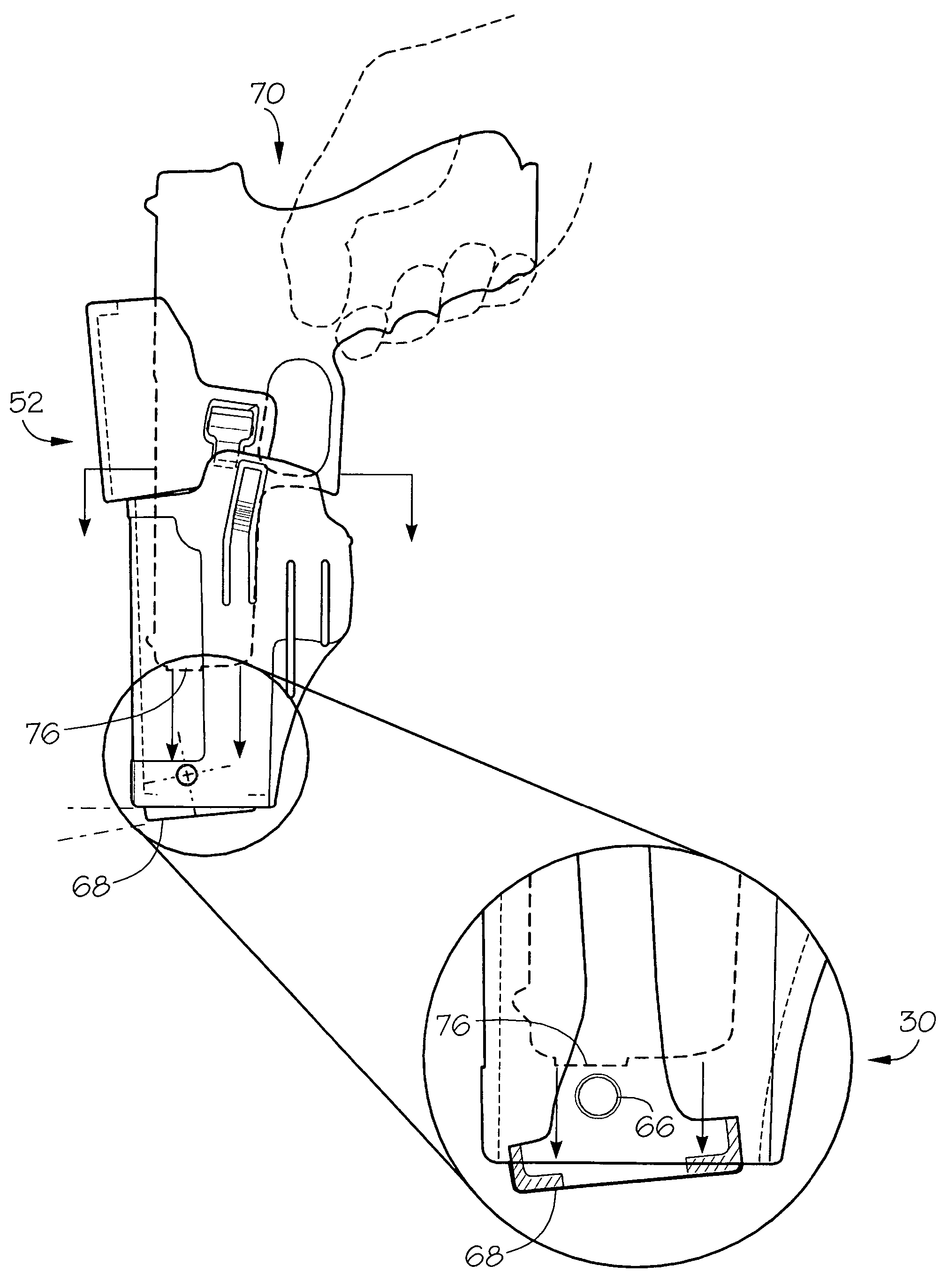
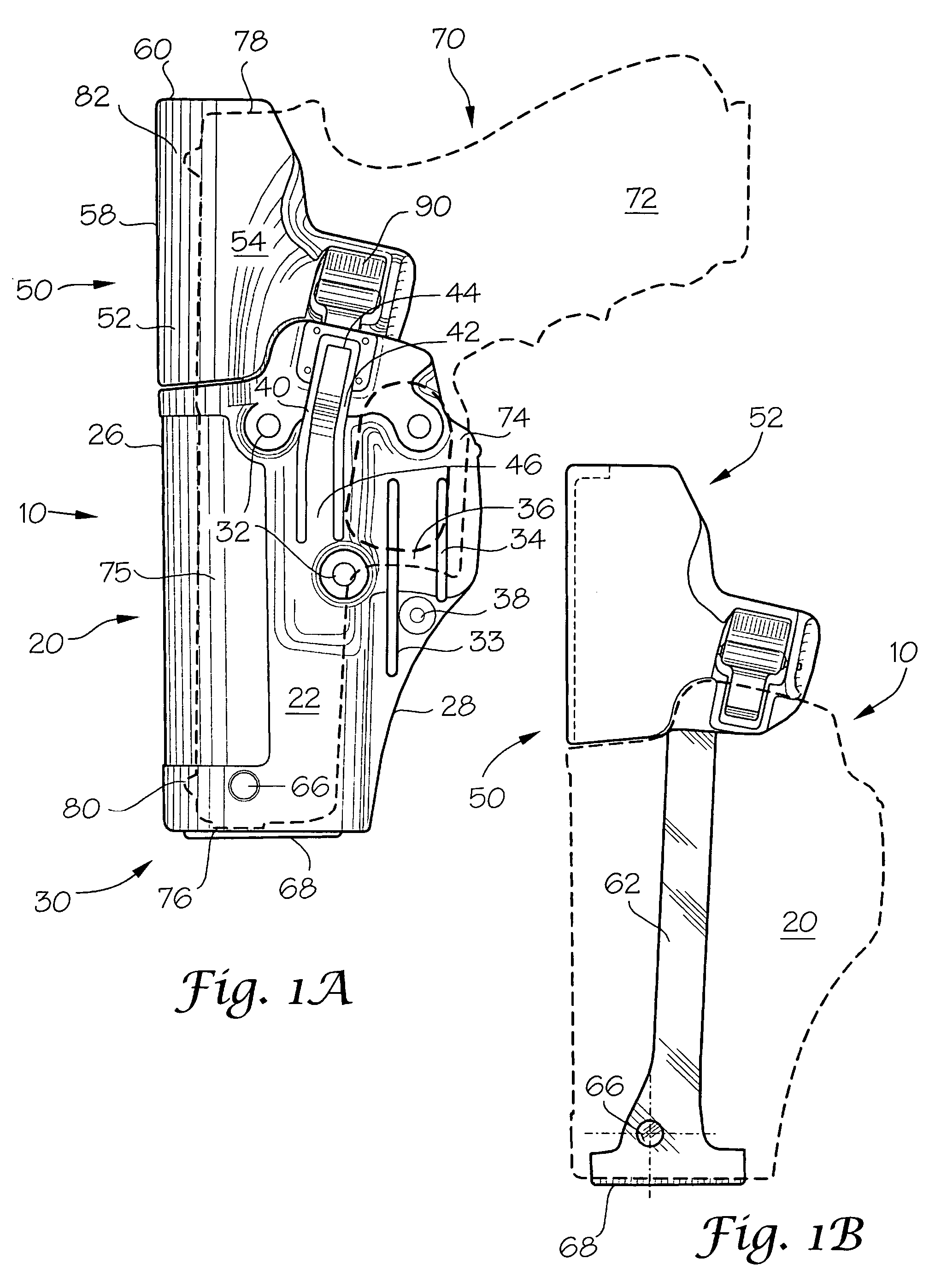
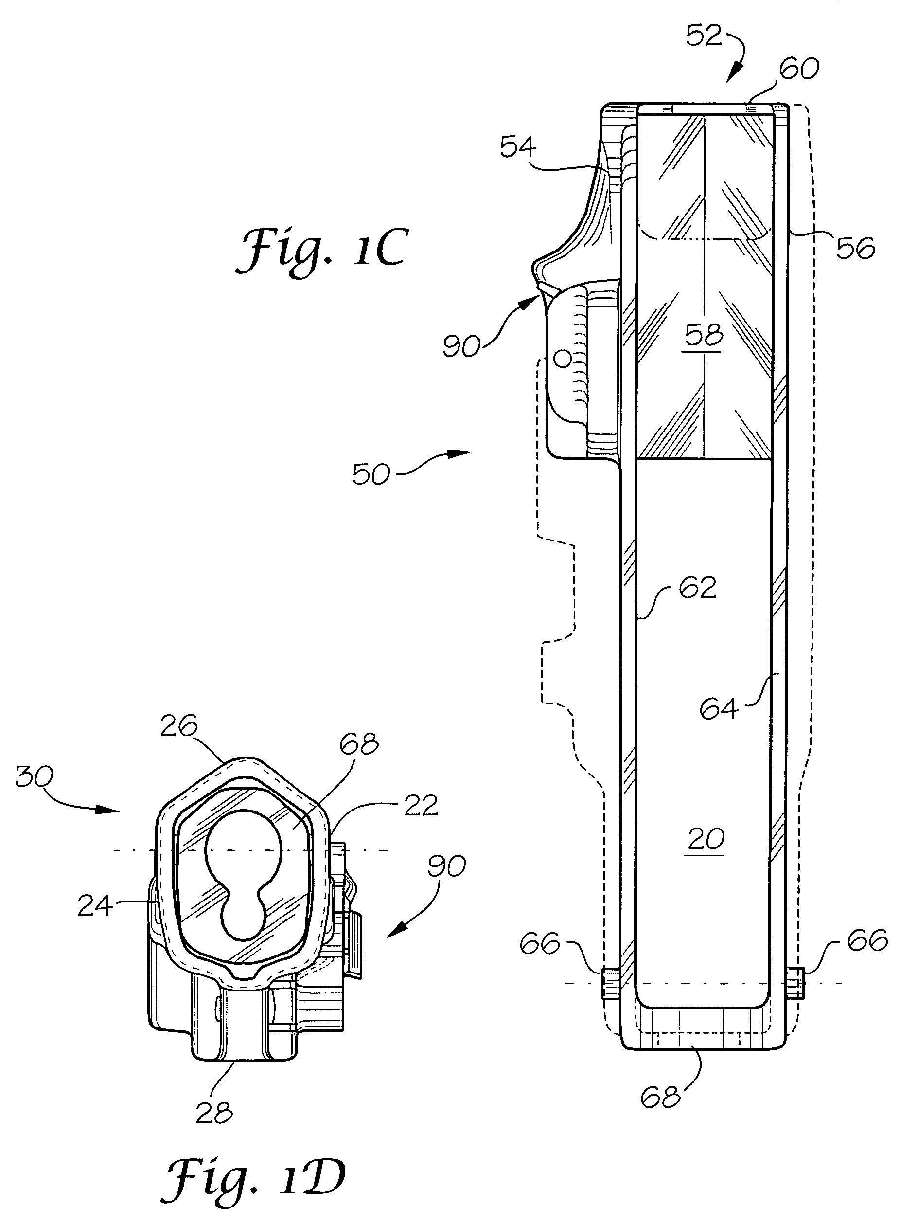
The present invention is a holster for a weapon that includes a body for holding the weapon, a hood assembly for securing the weapon, and a locking mechanism for securing the hood assembly when the weapon is held in the body. The hood assembly is pivotable between a closed position for securing the weapon and an open position for removal of the weapon. The locking mechanism automatically engages when the weapon is inserted into the body cavity and disengages when the weapon is absent. The hood assembly includes a retaining hood, an elongated pivot arm, and a lower pivot plate. The hood assembly is pivotably attached at a point on the pivot arm adjacent to the lower pivot plate to a point on the body adjacent to the lower portion of the body. The hood assembly is designed to automatically pivot to the closed position when the weapon is inserted into the body cavity. The holster is rigid and can be secured onto a belt, webbing, or platform. The technical effects of this invention include improved security and ease of use for weapon holders.

Problems solved by technology

More particularly, the invention relates to a holster that includes a hood for securing a weapon such that it may be easily removed from the holster by the wearer but removal by other than the wearer is very difficult.
However, a major problem with the existing prior art is that a criminal or adversary can easily remove the weapon from the holster during a struggle.
However, while the weapon is easily drawn by the user, upon reholstering the weapon the user must manually reposition the strap.
However, the present mechanism is not easily disengaged by anyone other than the wearer and, at a minimum, requires the use of both hands to release the weapon from the holster.

Method used


Image

  • Hooded holster
  • Hooded holster
  • Hooded holster

Examples


Embodiment Construction

[0041]The present invention is directed to a holster for a weapon which includes a body for receiving the weapon, a hood assembly for securing the weapon within the body, a lock for securing the hood assembly in a closed, weapon securing position, a lock release means for disengaging the lock and allowing the hood assembly to pivot to an open position for removal of the weapon, and means for automatically closing the hood assembly and engaging the lock when the weapon is reinserted, wherein the lock is engaged in a locked configuration while a weapon is held in the holster. Preferably, the hood assembly is biased to an open position a weapon is absent from the holster.

[0042]The present inventive holster is substantially rigid and is preferably formed of a polymeric material such as a polymeric composite. Alternate materials of construction may include one or more of the following: steel, aluminum, titanium, and / or other metals, as well as various alloys and composites thereof, glass...


PUM


Abstract

Disclosed is a holster for a weapon such as a handgun which includes a body defining a cavity for receiving and holding the weapon, a hood assembly pivotably connected to the body, the hood assembly pivotable between a closed position for securing the weapon within the body cavity and an open position for removal of the weapon, a locking mechanism securing the hood assembly in the closed position when a weapon is held in the body cavity, a release mechanism associated with the locking mechanism for releasing the hood assembly to the open position for removal of the weapon, and a mechanism for automatically pivoting the hood assembly to the closed position and thereby automatically engaging the locking mechanism upon insertion of the weapon into the body cavity, wherein the locking mechanism is biased to a locked configuration when the weapon is held in the body cavity.

Description

FIELD OF THE INVENTION[0001]The present invention is directed generally to a holster for a weapon such as a handgun and specifically to a rigid holster of the type that precludes unintended removal of the weapon.BACKGROUND OF THE INVENTION[0002]The present invention relates generally to a rigid holster for a weapon. More particularly, the invention relates to a holster that includes a hood for securing a weapon such that it may be easily removed from the holster by the wearer but removal by other than the wearer is very difficult.[0003]Previously, many holsters have been constructed with a strap for securing a weapon such as a handgun. Typically, the strap is looped across a hammer or other such part of the gun and includes a snap fastener at one end. The snap fastener is disengaged to remove the weapon from the holster.[0004]This configuration is dependable for securing the weapon. However, a major problem with the existing prior art is that a criminal or adversary can easily remov...

Claims


Application Information

Patent Timeline
Patent Type & Authority Patents(United States)
IPC IPC(8): F41C33/02
CPCF41C33/0209F41C33/0227F41C33/0254F41C33/0263
Inventor COOK, CLIFTON L.YEATES, ERIC M.GREGORY, THOMAS M.KINCAID, ROBERT A.
Owner VISTA OUTDOOR OPERATIONS
Learn More