

Low-profile, aimable lighting assembly
- Summary
- Abstract
- Description
- Claims
- Application Information
AI Technical Summary
Benefits of technology
Problems solved by technology
Method used
Image

Examples
Embodiment Construction
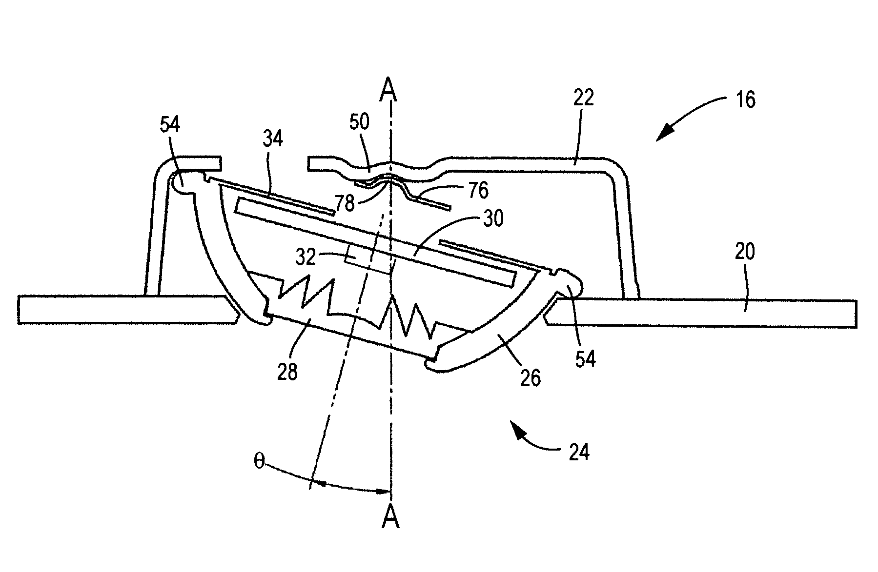
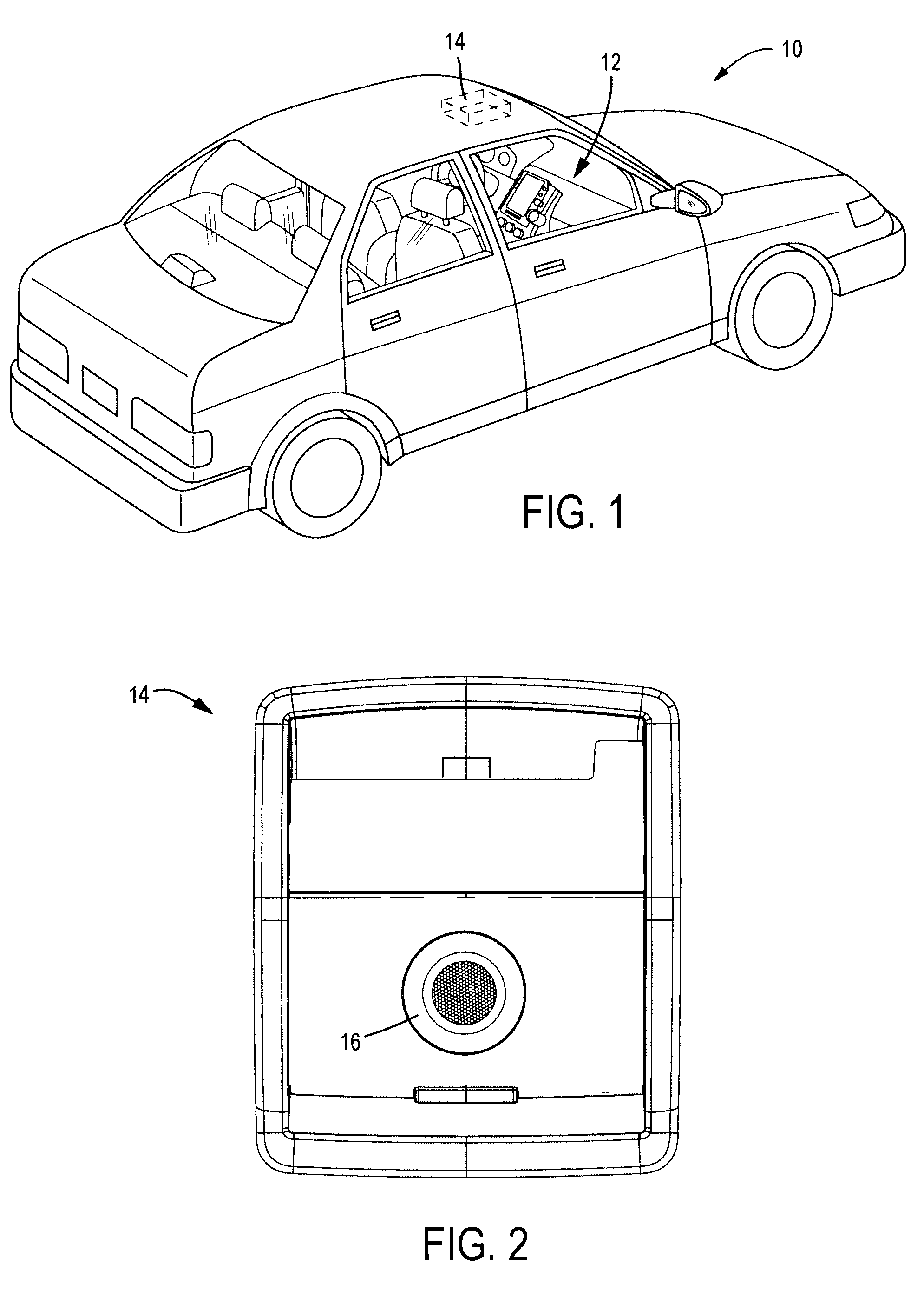
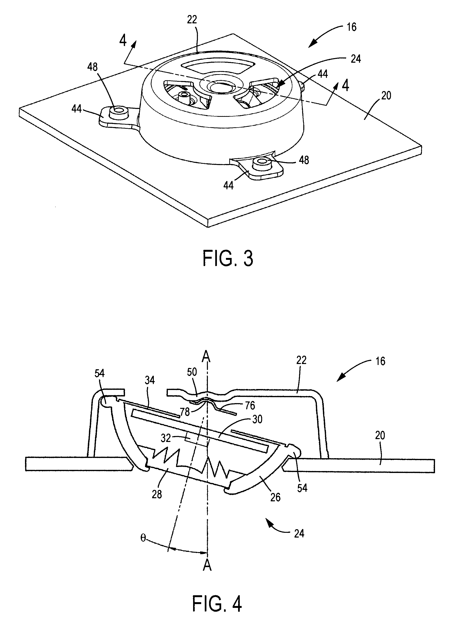
[0023]Referring to FIG. 1, a vehicle 10 is shown according to an exemplary embodiment. Vehicle 10 includes an interior portion 12 (e.g., a passenger compartment, etc.) and a console, shown as overhead console 14. While vehicle 10 is shown as an automobile in FIG. 1, it should be understood that according to various alternative embodiments, vehicle 10 may be any of a wide variety of vehicles, including sport utility vehicles, buses, recreational vehicles, airplanes, etc., and the teachings herein extend to all such applications.
[0024]Referring to FIG. 2, overhead console 14 (e.g., an overhead component, a panel, a headliner, etc.) is shown according to an exemplary embodiment. Overhead console 14 may include at least one lighting assembly 16 (e.g., a light fixture, reading light, overhead light, lamp assembly, etc.) that is intended to provide light to, for example, interior portion 12. While lighting assembly 16 is depicted in FIG. 2 as being a part of overhead console 14, it should...
PUM
 Abstract
Description
Claims
Application Information