Flow controlled blood pump system

a rotodynamic pump and flow control technology, applied in the direction of positive displacement liquid engines, machines/engines, therapy, etc., can solve the problems of unique interaction between the pump and the human circulatory system, the use of rotodynamic blood pumps as cardiac prostheses, and the variation of pressure and flow within the circulatory system, so as to improve the ability to deliver and control flow, increase the rotational speed of the impeller, and increase the pressure capacity of the pump

Inactive Publication Date: 2008-10-14
THE CLEVELAND CLINIC FOUND
View PDF19 Cites 45 Cited by
  • Summary
  • Abstract
  • Description
  • Claims
  • Application Information

AI Technical Summary

Benefits of technology

[0011]In accordance with another aspect of the invention, the resistance of the outflow conduit connecting the pump to the physiologic system is configured to partially insulate the pump outlet from the effects of pressure changes in the receiving end of the physiologic system. This results in the flow output of the pump system remaining closer to the mean set point over the full range of circulatory pressures.
[0012]According to yet another aspect of the invention the motor and its energy supply are controlled so that a decrease in load represented by falling flow results in an increase in the rotational speed of the impeller. This increases the pressure capability of the pump, improving its ability to deliver and control flow. An increase in flow has an exactly opposite effect.
[0013]According to yet another aspect of the invention, a switch permits the set point for the flow to be selected to suit the needs of different patients, or one patient during different phases of recovery.
[0014]A major benefit of the invention is the ability of the pumping system to maintain flow in a narrow range, safe and satisfactory for the served system, without the use of external sensors and control loops. Another benefit is the potential to shift the mean set point of flow by simple and reliable means. Other benefits and advantages for the subject invention will become apparent to those skilled in the art upon a reading and understanding of the specification.

Problems solved by technology

This action results in pressure and flow variations within the circulatory system.
The use of rotodynamic blood pumps as cardiac prosthesis presents unique problems with regard to the interaction between the pump and the human circulatory system.
Compared to the natural heart and some artificial hearts, conventional rotodynamic pumps are not as apt to respond correctly to changes in pressure and flow induced by the human circulatory system.
As a consequence, if the outlet pressure falls to a low level, an inappropriately designed and / or controlled rotodynamic pump may urge flow through the system until the inlet pressure falls to a correspondingly low and perhaps dangerous level, where upstream vascular structures may collapse from lack of blood pressure.
The change, which is compensatory from the pump's point of view, is potentially maladaptive relative to the needs of the physiologic system being supported.
In conventional pump constructions, the degree of maladaptivity of the pump is an inherent result, in part, of the nature of the performance curve associated with known pump designs.
This problem may be exacerbated if the natural heart retains some contractile function, causing the artificial pump pressure difference to oscillate between very low levels during natural heart systole, and high levels during diastole.
Within one heartbeat the system may experience excessive forward pumping, and reversed flow.
However, such techniques or devices are often complex and offer no economically feasible solution to the problems of providing low cost and dependable blood pumping systems.

Method used


Image

  • Flow controlled blood pump system
  • Flow controlled blood pump system
  • Flow controlled blood pump system

Examples


Embodiment Construction

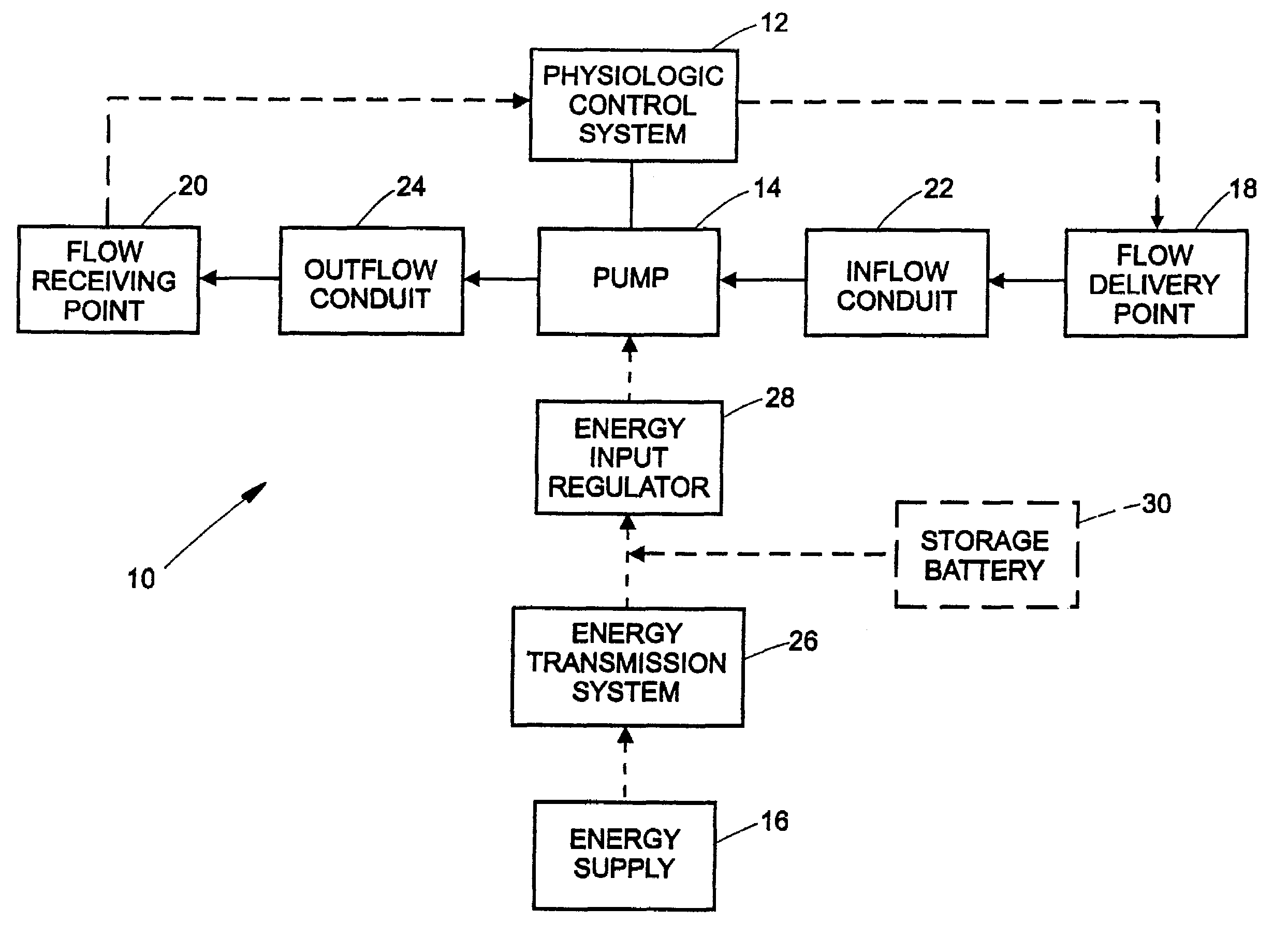
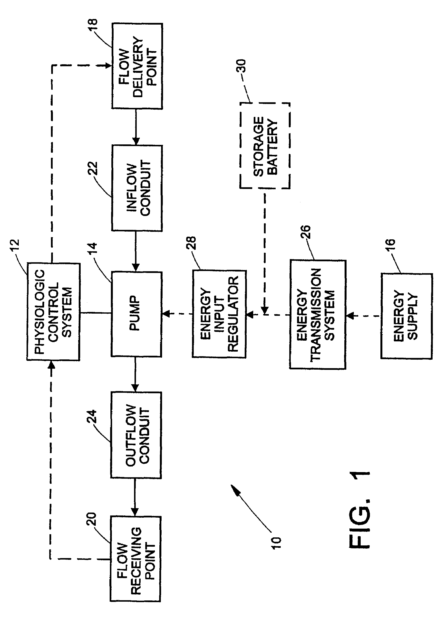
[0027]Referring now to the drawings wherein the showings are for purposes of illustrating the preferred embodiments of the invention only and not for purposes of limiting same, FIG. 1 shows block diagram of a blood pumping system according to the present invention. The human physiologic system is represented by block 12 and interfaces with pump 14 via flow receiving point 20 and flow delivery point 18. Typically, in a blood pump application, flow delivery point 18 may be a cannulation of the atrium or ventricle of the natural heart. Inflow conduit 22 may be a fluid carrying duct connecting the cannulation point to the inlet port of the pump. Outflow conduit 24 is another fluid carrying duct that connects pump outlet port to the flow receiving point 20. With a blood pump system, this point would usually be an anastomosis to a major artery.

[0028]The function of the biological control system 12 is well-known and a detailed discussion thereof is not necessary for an understanding of the...


PUM


Abstract

A system for pumping blood to assist or assume the cardiac function of a patient is characterized by a blood pump that exhibits a steep performance curve such that only small changes in pump flow occur for large changes in differential pressure across the pump. The pump therefore exhibits flow-limiting characteristics to protect the physiological system against harmful flow rates or pressures. Pump flow may also be limited by controlling the current provided to a driver from a power supply or by suitable restrictions within or external to the pump housing.

Description

BACKGROUND OF THE INVENTION[0001]This application is a continuation-in-part application of application U.S. Ser. No. 08 / 936,317, filed Sep. 24, 1997 now abandoned.[0002]The present invention relates to the art of pumping devices and cardiac prosthesis. More particularly, the present invention relates to motor-driven rotodynamic pumps for use as blood pumps in the human body and to control systems and techniques for such blood pumps.[0003]There has been much effort recently in the medical community to develop artificial devices and systems that are capable of assisting or completely assuming the cardiac function in patients having limited cardiac function or who have undergone removal of a diseased natural heart. Some of this effort has focused on duplicating the pulsatile mechanical action of the natural human heart. On the other hand, it has been recognized that human life may be sustained with non-pulsatile blood flow in the circulatory system. Accordingly, recent research has inc...

Claims


Application Information

Patent Timeline
Patent Type & Authority Patents(United States)
IPC IPC(8): F04B49/00A61M60/178A61M60/232F04D11/00A61M60/419A61M60/546A61M60/806A61M60/873
CPCA61M1/101A61M1/1031A61M2205/3334A61M2205/8243A61M60/419A61M60/422A61M60/898A61M60/148A61M60/546A61M60/232A61M60/178A61M60/806A61M60/873
Inventor SMITH, WILLIAM A.GOLDING, LEONARD A. R.
Owner THE CLEVELAND CLINIC FOUND
Why Eureka
Try Eureka