Projection lens

a projection lens and lens body technology, applied in the field of projection lenses, can solve the problems of deterioration of resolution attribution attributable to chromatic aberration, which has been taken as a problem, and the difficulty of rendering the entire projection system compact, so as to compensate for the curvature of field

Inactive Publication Date: 2008-10-14
FUJI PHOTO OPTICAL CO LTD
View PDF5 Cites 5 Cited by
  • Summary
  • Abstract
  • Description
  • Claims
  • Application Information

AI Technical Summary

Benefits of technology

[0044]An aspherical lens is disposed in each of: a side of the first lens group closest to the enlargement side; and the second lens group, and the aspherical lens placed on a side of the first lens group closest to the enlargement side is configured so as to be able to move in the direction of an optical axis of the first lens group according to a change in projection distance, thereby enabling compensation for a curvature of field induced by the change in projection distance. Moreover, the first lens group can be configured so as to be able to move in the direction of the optical axis of the first lens group, to thus enable adjustment of a focus.

Problems solved by technology

In particular, in the case of a wide-angle projection lens, deterioration of resolution attribution attributable to a chromatic aberration has been taken as a problem.
Since it is difficult to fulfill both such desires, a projection lens fulfilling the desires on a high level have never been realized thus far.
However, the projection lens does not have any space for arrangement of the optical path deflection section, such as a mirror, and hence difficulty is encountered in rendering the entire projection system compact.
However, compensation of the chromatic aberration arising at the time of use of high-resolution light valves is insufficient.
Moreover, since an enlargement-side lens is large, difficulty is encountered in making an attempt to render the entire projection lens system compact.

Method used


Image

  • Projection lens
  • Projection lens
  • Projection lens

Examples


example 1

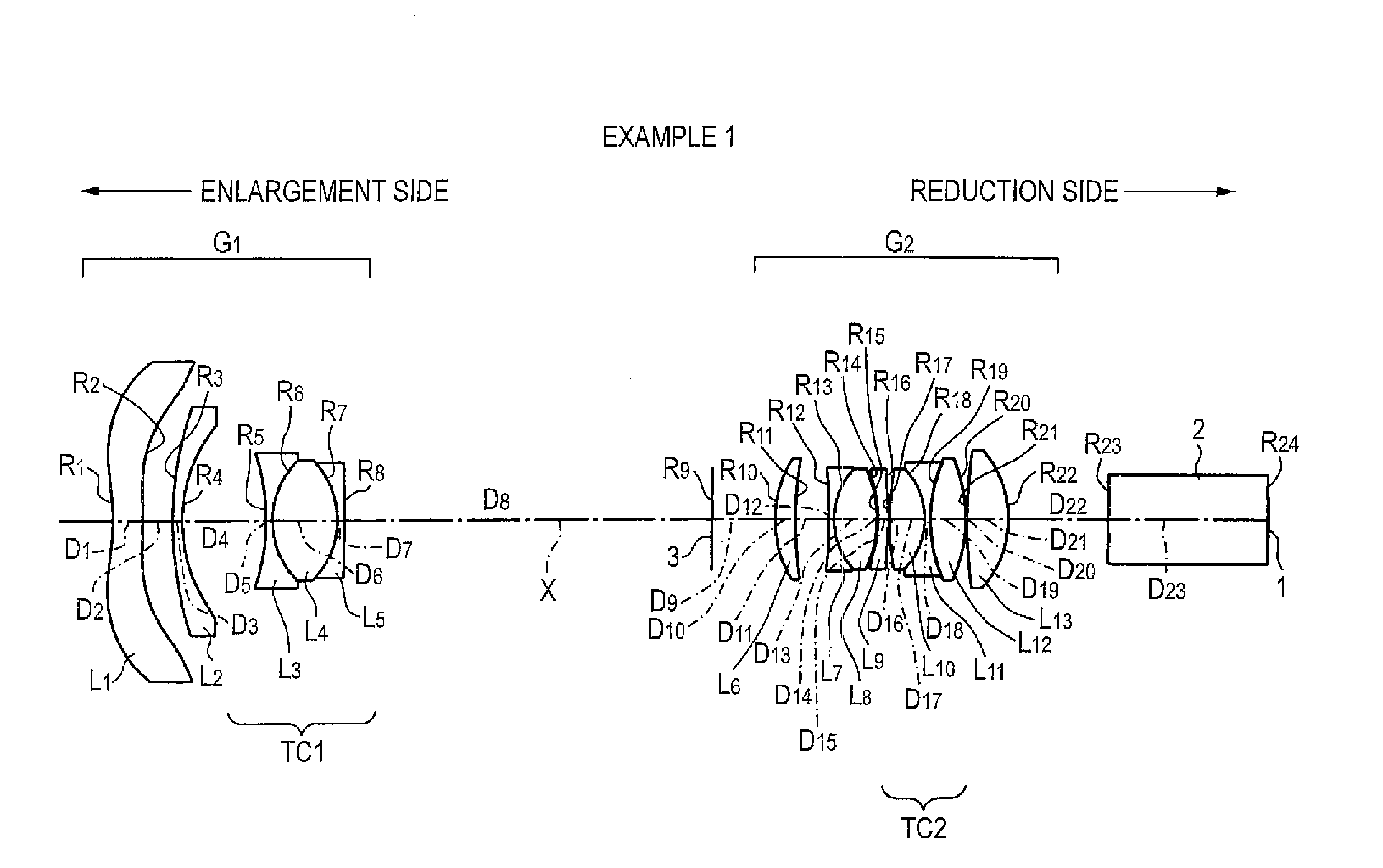
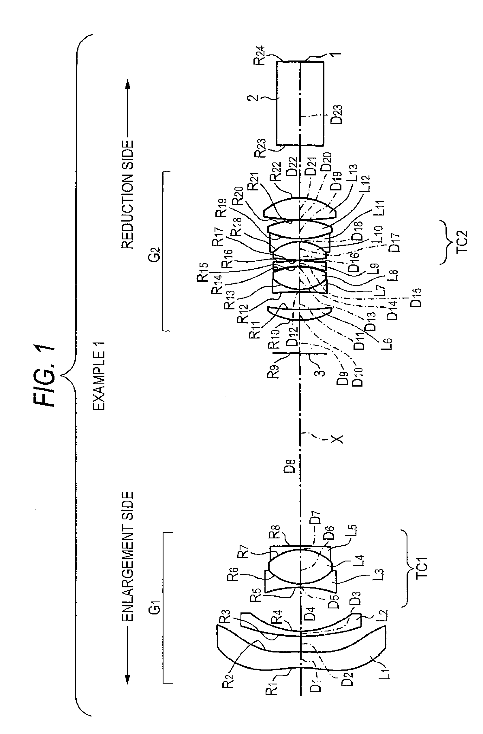
[0086]As shown in FIG. 1, the projection lens of Example 1 includes the first lens group G1 having negative refractive power, the aperture diaphragm 3, and the second lens group G2 having positive refractive power, which are arranged in order from the enlargement side. The reduction side of the projection lens is made essentially telecentric.

[0087]In the first lens group G1, the first lens L1 formed from an aspherical lens whose convex surface is oriented toward the enlargement side, the second lens L2 formed from a negative meniscus lens whose concave surface is oriented toward the reduction side, and the cemented triplet lens TC1 formed by sandwiching the fourth lens L4 formed from one biconvex lens between the third and fifth lenses L3 and L5 are arranged in order from the enlargement side.

[0088]In the meantime, in the second lens group G2, there are arranged the sixth lens L6 formed from a positive meniscus lens whose convex surface is oriented toward the enlargement side, the s...

example 2

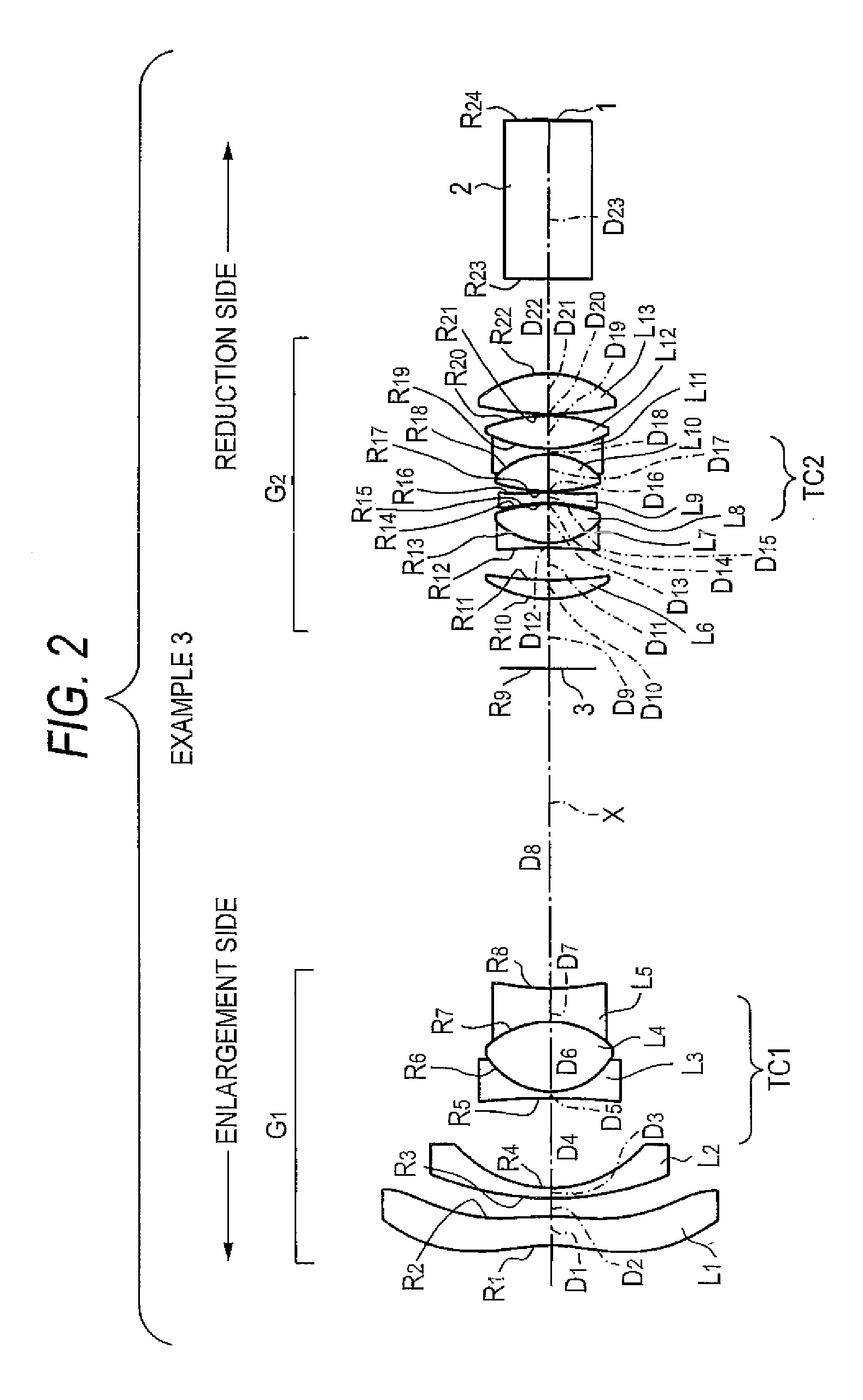
[0104]A projection lens of Example 2 is essentially identical in configuration to a projection lens of Example 3 which is shown in FIG. 2 and which will be described later. FIG. 2 is used as an example overview, and explanations about common elements are omitted.

[0105]Specifically, in the projection lens of Example 1, the fifth lens L5 is embodied as a negative meniscus lens whose concave surface is oriented toward the enlargement side. In contrast, the present example and subsequent examples differ from Example 1 in that the fifth lens L5 is embodied by a biconcave lens. In other respects, all of the examples have a common basic configuration.

[0106]An upper row of Table 3 shows a value of a radius of curvature R of each of lens surfaces of the projection lens of Example 2, a value of on-axis surface spacing D of each of the lenses, a value of a refractive index Nd achieved along d-line of each of the lenses, and a value of an Abbe number νd achieved along d-line of each of the lens...

example 3

[0111]A projection lens of Example 3 is as shown in FIG. 2. The projection lens is essentially identical in configuration to the projection lens of Example 1, and explanations of common elements are omitted.

[0112]An upper row of Table 5 shows a value of a radius of curvature R of each of lens surfaces of the projection lens of Example 3, a value of on-axis surface spacing D of each of the lenses, a value of a refractive index Nd achieved along d-line of each of the lenses, and a value of an Abbe number νd achieved along d-line of each of the lenses. Lower rows of Table 5 show a projection distance (spacing between a conjugate position on the enlargement side and the first surface of the lens).

[0113]

TABLE 5Focal Length F = 1.00Surface Nos.RDNdνd 1*−7.2871.1731.4910057.6 2*−12.9240.734 312.8610.4211.8466623.8 45.1993.657 5−27.4760.2611.7130053.9 63.0852.8171.6398034.5 7−3.8551.3411.8040046.6 810.98413.033 9 (STO)∞2.857104.6690.7781.8466623.81116.9851.31212−21.4730.2091.8040046.6133.07...


PUM


Abstract

A first lens group having a negative refractive power, an aperture diaphragm, and a second lens group having a positive refractive power are arranged in order from an enlargement side. A reduction side of a projection lens is made essentially telecentric. Further, cemented triplet lenses, each of which includes cemented three lenses, are provided in the first lens group and the second lens group, respectively. Further, air spacing which enables placement of a mirror is ensured between the first lens group and the second lens group. Moreover, specific conditional expressions for the lens are satisfied.

Description

BACKGROUND OF THE INVENTION[0001]1. Field of the Invention[0002]The present invention relates to a projection lens which projects in an enlarged manner display information, and the like, from a light bulb such as a liquid-crystal display element; and more particularly to a projection lens suitable for use with a display device of rear projection type, such as rear projection TV, and a projection-typed display device using the projection lens.[0003]2. Description of the Related Art[0004]A projection display device of front type and a projection display device of rear type have hitherto been known as a projection-type display device. In the display device of front type, a projection lens is disposed on the same side where a viewer is located with respect to a screen, and light emitted from the projection lens is projected on a reflection-type screen, to thus produce an image on the screen. In the display device of rear type, the projection lens is disposed opposite the viewer with the...

Claims


Application Information

Patent Timeline
Patent Type & Authority Patents(United States)
IPC IPC(8): G02B3/00G02B3/02G02B9/04
CPCG02B13/22G03B21/10
Inventor NAGATOSHI, YUKIKO
Owner FUJI PHOTO OPTICAL CO LTD
Why Eureka
Try Eureka