Printing device, printing device control program and method, and printing data generation device, program, and method

a printing device and control program technology, applied in the direction of printing, other printing devices, etc., can solve the problems of shortening the printing time compared with other printing devices such as electrophotographic laser printers or others, affecting the quality of printing images, and affecting the printing image quality, so as to reduce the degradation of printing image quality

Inactive Publication Date: 2008-10-21
SEIKO EPSON CORP
View PDF16 Cites 10 Cited by
  • Summary
  • Abstract
  • Description
  • Claims
  • Application Information

AI Technical Summary

Benefits of technology

[0022]An advantage of some aspects of the invention is to provide a printing device, a printing device control program and method, and a printing data generation device, program, and method, all of which are newly developed and capable of stopping image degradation or making image degradation less conspicuous that is caused by a banding problem resulted from ink deflection, and ink discharge failures.

Problems solved by technology

There is a problem with such an ink jet printer of a type performing printing with the printer head reciprocating on the carriage in the direction perpendicular to the printing paper.
This results in a drawback of a longer printing time compared with other types of printing device such as electrophotographic laser printers or others, e.g., copying machines.
The issue with such an ink jet printer is the manufacturing deviation observed in the printing head that serves an essential role for the printer.
In such a configuration, the nozzle may be partially misaligned so that the ink discharge direction is incorrectly angled, or the nozzles may not be correctly disposed as they are expected to be so that the nozzles resultantly fail in forming dots at their ideal positions, i.e., causes ink deflection.
As a result, an image part printed by such a faulty nozzle suffers a printing failure, i.e., so-called banding (streaking) problem, resultantly reducing the printing quality considerably.
When the amount of ink coming from any of the nozzles is not ideal and is a lot, the part for the nozzle suffers from dark streaks, and when the amount of ink is little, the part suffers from white streaks.
Such a banding problem is often observed in “line head printers” in which a printing head or a printing medium is fixed, i.e., printing with a single scan, compared with the above-described “multi-path printers” (serial printers).
However, from the perspective of manufacturing cost, the printing quality, the technology, or others, it is found difficult to provide a printing head perfectly free from the banding problem.
In consideration thereof, such technologies are not suitable for printing required to be high in image quality and printing quality as color photograph printing.
Another issue is with the technology of allocating information about any discharge-faulty nozzles to right and left thereof to prevent white streaks in parts high in density.
If this technology is applied to solve the above-described ink deflection problem, white streaks are actually reduced but the banding problem still remains unsolved in parts high in density.
The related art of Patent Document 3 causes no problem with printing subjects if they are filled-in images, but cannot be used if printing subjects are of halftone.
However, if with an image of many colors, i.e., one color next to another, the technology also fails to solve the problem of hue change in the image.
The related art of Patent Document 4 also raises an issue of complicating the feeding-back process that is expected to be appropriately executed against the problem of not deriving ideal dot formation details, and such an issue is difficult to solve.
The degradation of printing quality includes, for example, white and dark streaks caused by a banding problem, which is resulted from ink deflection due to nozzles whose dot formation positions are not ideal.
The expression of “banding problem” means a printing failure of white and dark streaks observed together in the printing result.
This is resulted from so-called ink deflection due to nozzles varying in dot formation positions, and being not at their ideal positions.
This is because the wider neighboring range resultantly increases the size of the region with image degradation, e.g., the granularity being more noticeable.
That is, the dot-to-dot distance being wider than ideal means that the nozzle in charge of dot formation for the area is suffering from ink deflection, and means a high risk of white streaks for the part showing the wider dot-to-dot distance.
That is, the dot-to-dot distance being narrower than ideal means that the nozzle in charge of dot formation for the area is suffering from ink deflection, and means a high risk of dark streaks for the part showing the narrower dot-to-dot distance.
These streaks are those caused by a banding problem, which is often observed in line head printing heads that complete printing with a single scan, i.e., a single path.
The above-described banding problem is pretty common with printing heads of line head type, but printing heads of multi-path type are not yet free from such a problem.
These streaks are those caused by a banding problem, which is observed in multi-head printing heads.

Method used


Image

  • Printing device, printing device control program and method, and printing data generation device, program, and method
  • Printing device, printing device control program and method, and printing data generation device, program, and method
  • Printing device, printing device control program and method, and printing data generation device, program, and method

Examples


first embodiment

[0282]Described below is a first embodiment of the invention referring to the accompanying drawings. FIGS. 1 to 13C are all a diagram showing the first embodiment of the invention, i.e., a printing device, a printing device control program and method, and a printing data generation device, program, and method.

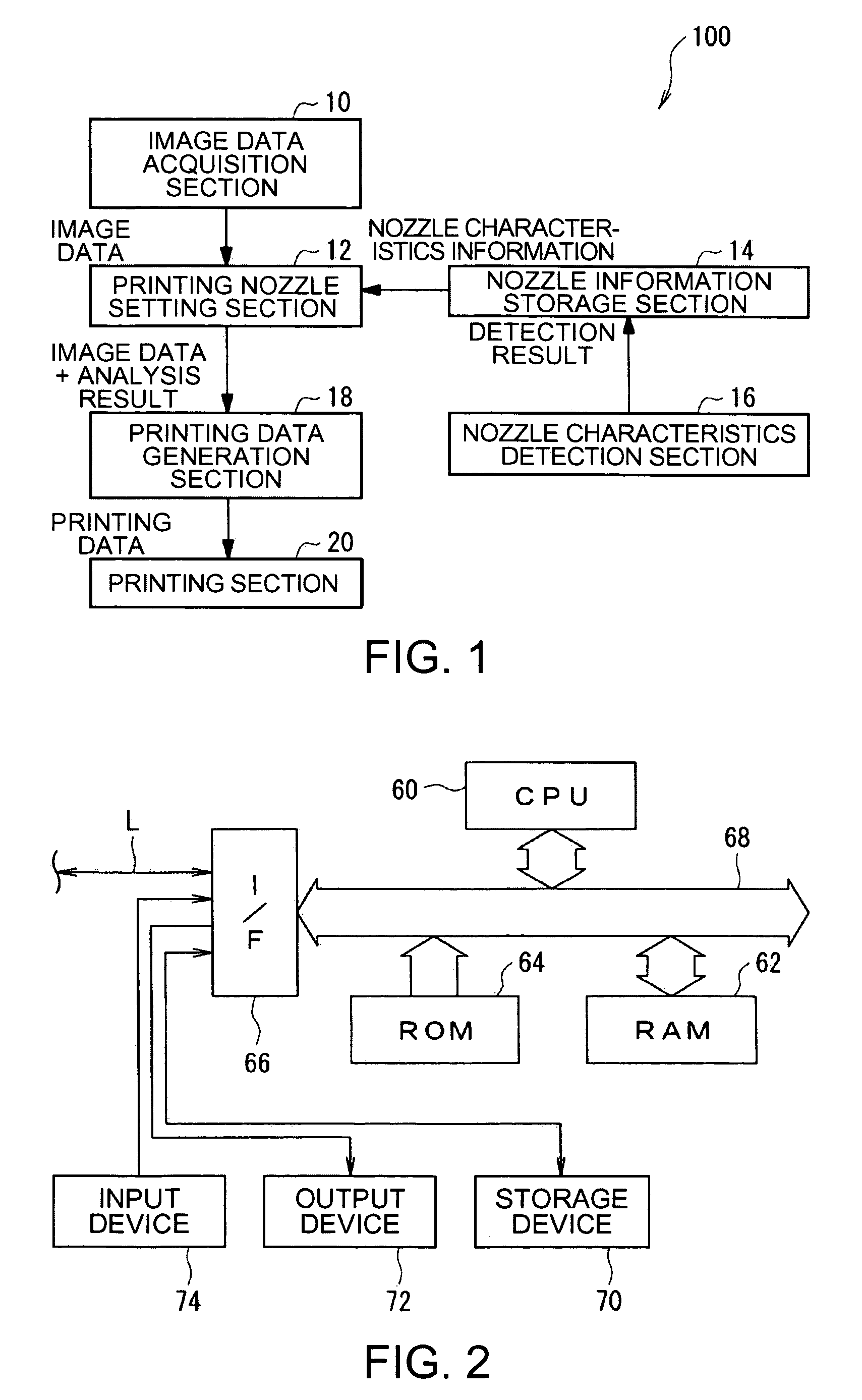
[0283]Described first is the configuration of a printing device 100 of the invention by referring to FIG. 1. FIG. 1 is a block diagram showing the configuration of the printing device 100 of the invention.

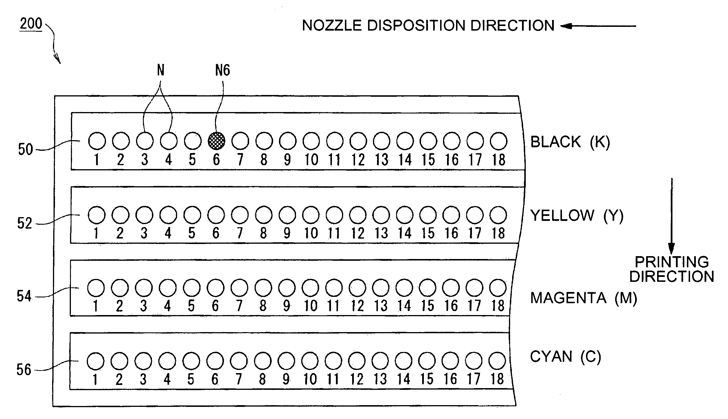
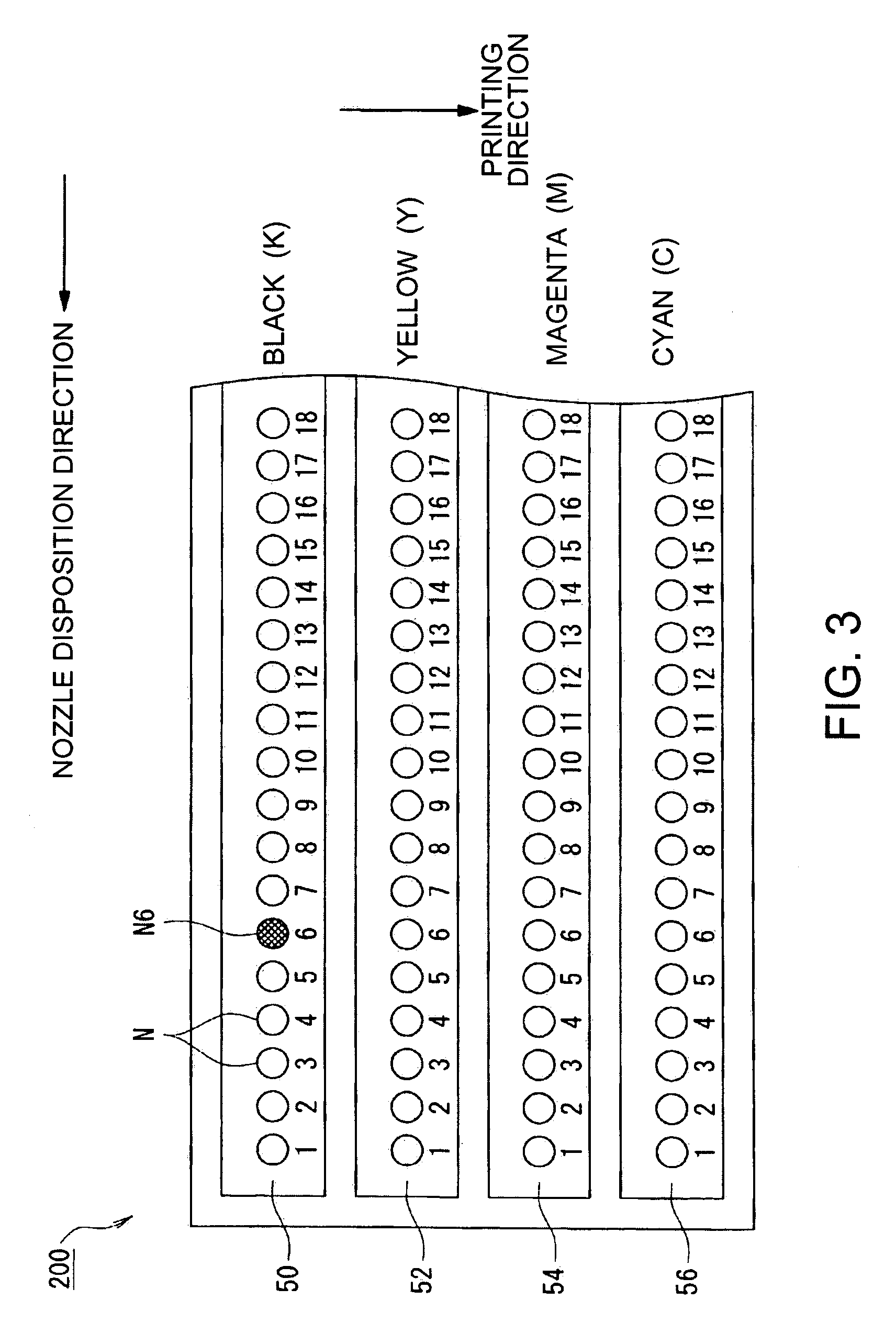
[0284]As shown in FIG. 1, the printing device 100 is of a line-head type, configured to include: an image data acquisition section 10; a printing nozzle setting section 12; a nozzle information storage section 14; a nozzle characteristics detection section 16; a printing data generation section 18; and a printing section 20. More specifically, the image data acquisition section 10 acquires image data from any external devices, storage devices, or others. The image data is the ...

second embodiment

[0355]Described next is a second embodiment of the invention by referring to the accompanying drawings. FIGS. 14 to 17 are all a diagram showing the second embodiment of the invention, i.e., a printing device, a printing device control program and method, and a printing data generation device, program, and method.

[0356]In the second embodiment, the printing device and the computer system both are in the similar configuration as those in the first embodiment shown in FIGS. 1 and 2. The second embodiment is different from the first embodiment in the respect that the printing data generation process in step S110 of FIG. 5 is replaced with the process of FIG. 14.

[0357]Although the printing data generation process of FIG. 14 is the same as that of the first embodiment in principle, a difference lies in the following respects. That is, a pixel column corresponding to a nozzle causing ink deflection is determined with a dot size-increase ratio. As to the pixel column, every pixel is subjec...

third embodiment

[0391]Described next is a third embodiment of the invention by referring to the accompanying drawings. FIGS. 18 to 23C are all a diagram showing the third embodiment of the invention, i.e., a printing device, a printing device control program and method, and a printing data generation device, program, and method.

[0392]The printing device of the third embodiment is similar in configuration as the printing device 100 of FIG. 1 in the first and second embodiments, except that the nozzle setting section 12 is not provided. The computer system of the third embodiment is similar to that of FIG. 1 in the first and second embodiments, and the printing head is similar to that of FIG. 3 in the first and second embodiments. In the present embodiment, the printing process of FIG. 5 in the first and second embodiments is replaced with the process of FIG. 19, and the printing data generation process of FIG. 6 or 14 is replaced with the process of FIG. 20.

[0393]The third embodiment is different fr...


PUM


Abstract

A printing device that prints an image onto a printing medium using a printing head that includes a plurality of nozzles each being capable of dot formation to the printing medium. The printing device includes: an image data acquisition unit that acquires image data showing pixel values of M (M≧2) for the image; a displacement amount information storage unit that stores information about an amount of a displacement observed to the printing medium by each of the nozzles between an actual dot formation position and an ideal dot formation position; a printing data generation unit that generates printing data including information about dot formation details based on the acquired image data and the displacement amount information for each of the pixel values, and for use as the information about the dot formation details, generates information about reducing degradation of printing image quality due to a banding problem caused by the displacement between the actual dot formation position and the ideal dot formation position, and exercises control over generating the degradation-reducing information based on the displacement amount information; and a printing unit that prints, based on the printing data, the image onto the printing medium using the printing head.

Description

RELATED APPLICATIONS[0001]This application claims priority to Japanese Patent Application Nos. 2004-379210 filed Dec. 28, 2004 and 2005-265356 filed Sep. 13, 2005 which are hereby expressly incorporated by reference herein their entirety.BACKGROUND[0002]1. Technical Field[0003]The present invention relates to a printing device for use with printers of facsimile machines, copying machines, OA equipment, and others, a printing device control program and method, and a printing data generation device, program, and method. More specifically, the present invention relates to a printing device of an ink jet type that is capable of text and image rendering onto a printing paper (printing medium) through discharge of liquid ink particles of various colors, a control program and method for such a printing device, and a printing data generation device, program, and method.[0004]2. Related Art[0005]Described below is a printing device, specifically a printer of an ink jet type (hereinafter, ref...

Claims


Application Information

Patent Timeline
Patent Type & Authority Patents(United States)
IPC IPC(8): B41J2/205
CPCB41J2/0451B41J2/04558B41J2/04561B41J2/04581B41J2/04593B41J2/2135B41J29/393
Inventor ARAZAKI, SHINICHI
Owner SEIKO EPSON CORP
Why Eureka
Try Eureka