Printing device, printing device control, program and method, and printing data generation device, program and method

a printing device and control program technology, applied in printing, typewriters, other printing apparatuses, etc., can solve the problems of long printing time drawback, type of printing device, manufacturing deviation observed in the printing head, etc., to stop image degradation and make image degradation less conspicuous

Inactive Publication Date: 2006-06-15
SEIKO EPSON CORP
View PDF4 Cites 14 Cited by
  • Summary
  • Abstract
  • Description
  • Claims
  • Application Information

AI Technical Summary

Benefits of technology

[0022] An advantage of some aspects of the invention is to provide a printing device, a printing device control program and method, and a printing data generation device, program, and method, all of which are newly developed and capable of stopping image degradation or making image degradation less conspicuous that is caused by a banding problem resulting from ink deflection, and ink discharge failures.

Problems solved by technology

There is a problem with ink jet printers that perform printing with the printer head reciprocating on the carriage in the direction perpendicular to the printing paper.
This results in a drawback of a longer printing time as compared with other types of printing devices such as electrophotbgraphic laser printers or others, e.g., copying machines.
The issue with such ink jet printers is the manufacturing deviation observed in the printing head that serves an essential role for the printer.
In such a configuration, a nozzle may be partially misaligned so that the ink discharge direction is incorrectly angled, or the nozzles may not be correctly disposed as they are expected to be so that the nozzles resultantly fail in forming dots at their ideal positions, i.e., ink deflection.
As a result, an image part printed by such a faulty nozzle suffers a printing failure, i.e., a so-called banding (streaking) problem, resultantly reducing the printing quality considerably.
When the amount of ink coming from any of the nozzles is not ideal and is a lot, the part for the nozzle suffers from dark streaks, and when the amount of ink is little, the part suffers from white streaks.
Such a banding problem is often observed in “line head printers” in which a printing head or a printing medium is fixed, i.e., printing with a single scan, compared with the above-described “multi-path printers” (serial printers) This is because the multi-path printers are adopting the technology of making white streaks less noticeable utilizing frequent reciprocating movements of the printing head.
However, from the perspective of manufacturing cost, the printing quality, the technology, or others, it is found difficult to provide a printing head perfectly free from the banding problem.
In consideration thereof, such technologies are not suitable for printing required to be high in image quality and printing quality as color photograph printing.
Another issue is with the technology of allocating information about any discharge-faulty nozzles to the right and left thereof to prevent white streaks in parts high in density.
If this technology is applied to solve the above-described ink deflection problem, white streaks are actually reduced but the banding problem still remains unsolved in parts high in density.
The related art of Patent Document 3 causes no problem with printing subjects if they are filled-in images, but cannot be used if printing subjects are of halftone.
However, if with an image of many colors, i.e., one color next to another, the technology also fails to solve the problem of hue change in the image.
The related art of Patent Document 4 also raises an issue of complicating the feeding-back process that is expected to be appropriately executed against the problem of not deriving ideal dot formation details, and such an issue is difficult to solve.
One is a printing failure of white and dark streaks observed together in the printing result.
This results from ink deflection due to nozzles varying in dot formation details.
The other is a printing failure caused by varying ink discharge amount.
This is because, if this vicinity range is too wide, it resultantly increases the not-that-good granularity.
These streaks are those caused by a banding problem, which is often observed in line head printing heads that complete printing with a single path.
These streaks are those caused by a banding problem, which is often observed in line head printing heads that complete printing with a single scan, i.e., a single path.
The above-described banding problem is relatively common with printing heads of line head type, but printing heads of multi-path type are not yet free from such a problem.

Method used


Image

  • Printing device, printing device control, program and method, and printing data generation device, program and method
  • Printing device, printing device control, program and method, and printing data generation device, program and method
  • Printing device, printing device control, program and method, and printing data generation device, program and method

Examples


second embodiment

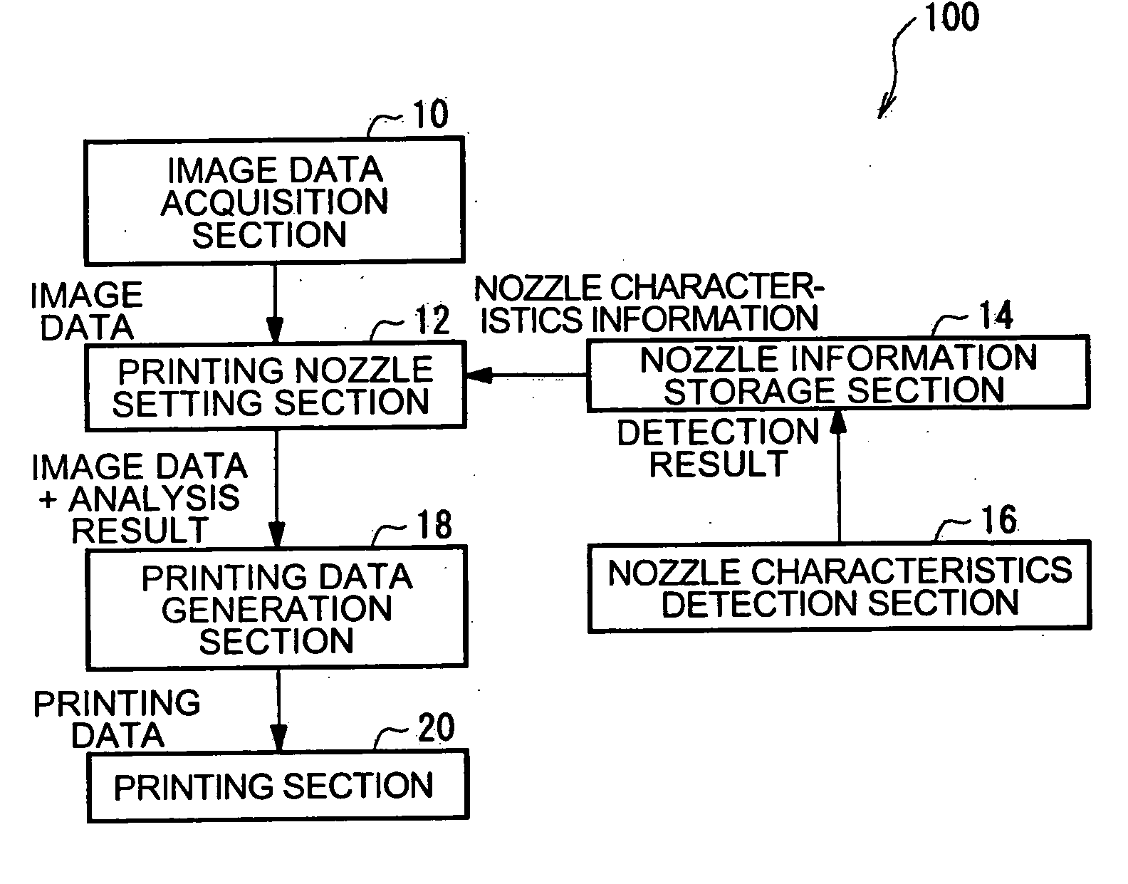
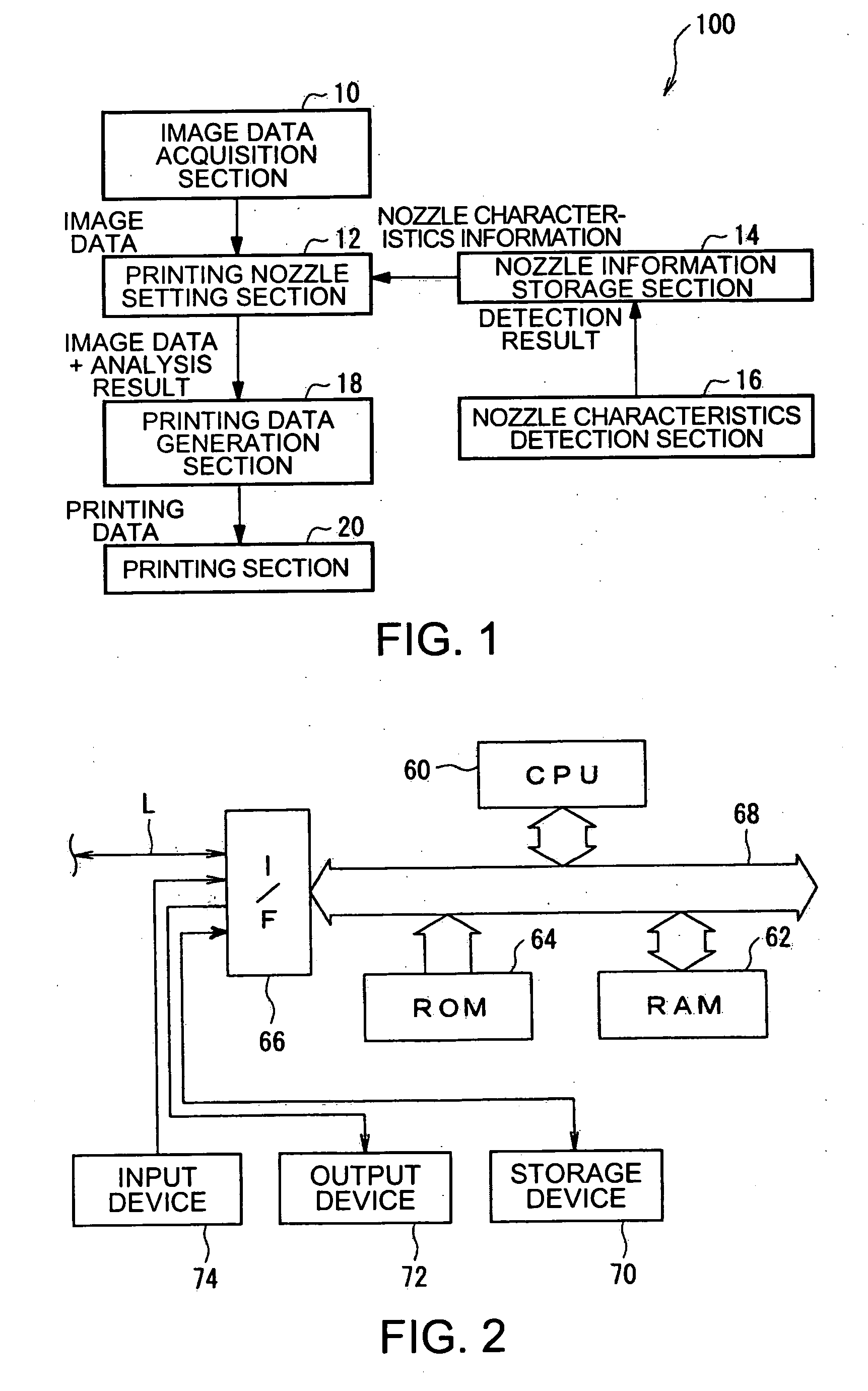
[0321] Described next is a second embodiment of the invention by referring to the accompanying drawings. FIGS. 13 and 14 are both diagrams showing the second embodiment of the invention, i.e., a printing device, a printing device control program and method, and a printing data generation device, program, and method.

[0322] The second embodiment is different from the first embodiment in the respect that a nozzle disuse setting is made for every other line of the image data. In the following, only the differences from the first embodiment are described thereby avoiding redundant description.

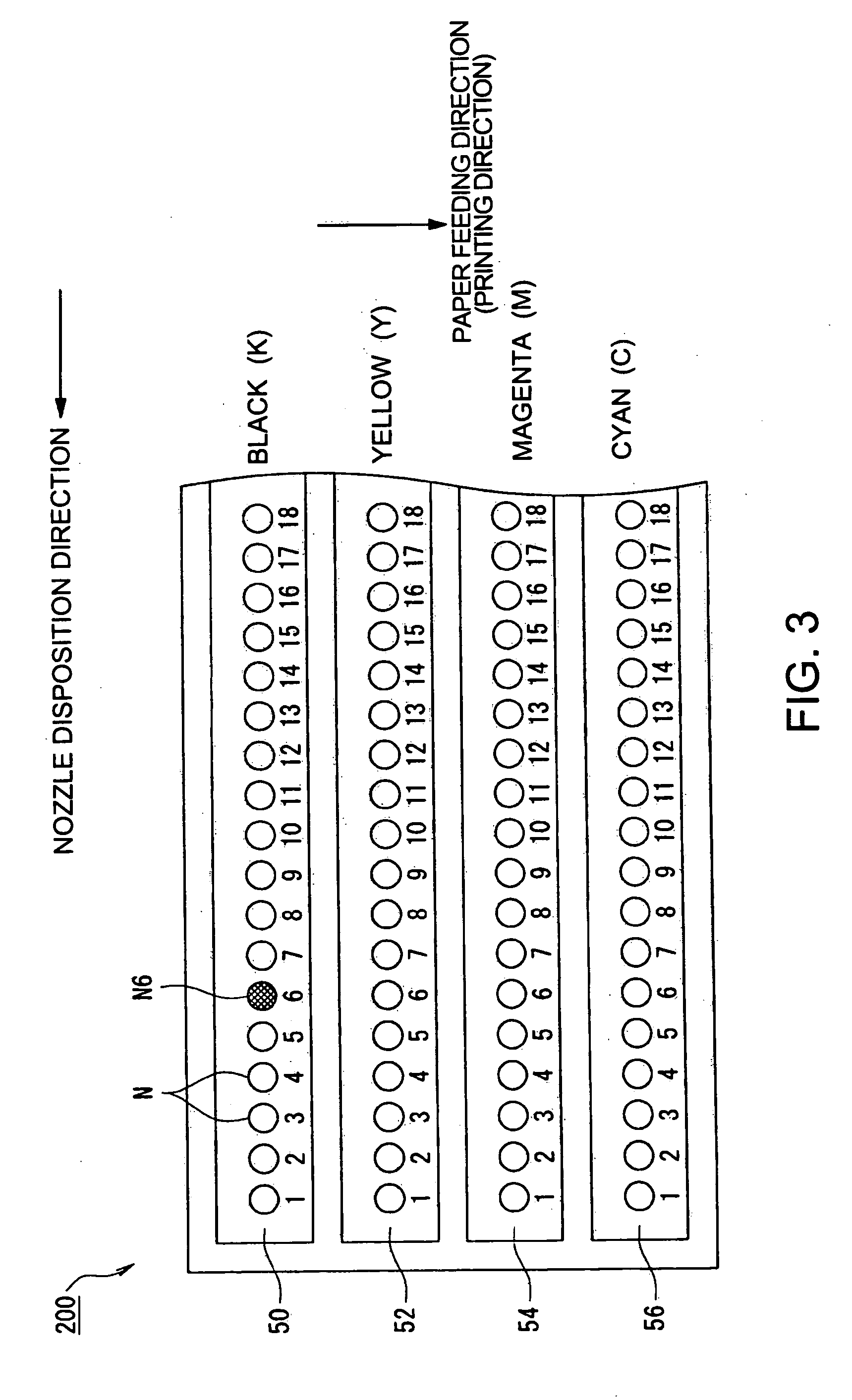
[0323] In step S202, based on the analysis result of step S200 and the nozzle characteristics information read from the nozzle information storage section 14, the printing nozzle setting section 12 makes a setting of whether the pixel data of a predetermined region is used with the corresponding nozzle N. After such setting-making, the procedure goes to step S204. In the present embodiment, a nozz...

third embodiment

[0335] Described next is a third embodiment of the invention by referring to the accompanying drawings. FIGS. 15 to 17 are all diagrams showing the third embodiment of the invention, i.e., a printing device, a printing device control program and method, and a printing data generation device, program, and method.

[0336] The third embodiment is different from the first and second embodiments in the respect that a nozzle disuse setting is made by selecting not-to-be-used nozzles at random from a faulty nozzle and its neighboring nozzles for every line of the image data. In the following, only the differences from the first and second embodiments are described thereby avoiding redundant description.

[0337] In step S202, based on the analysis result of step S200 and the nozzle characteristics information read from the nozzle information storage section 14, the printing nozzle setting section 12 makes a setting of whether the pixel data of a predetermined region of the image data is used ...


PUM


Abstract

A printing device including: an image data acquisition unit acquiring image data corresponding to pixels of the image; a printing data generation unit generating, based on the acquired image data, printing data including information about dot formation details based on the pixels for each of the nozzles; a nozzle information storage unit storing information about nozzles whose dot formation details are different from predetermined dot formation details; and a printing unit printing, based on the printing data, the image onto a printing medium using a printing head. By referring to the nozzle information storage unit, the printing data generation unit generates printing data providing a lower resolution for the image to be printed by at least either the nozzle of different dot formation details or neighboring nozzles compared with a resolution of the image data acquired by the image data acquisition unit corresponding to the nozzle used for printing.

Description

RELATED APPLICATIONS [0001] This application claims priority to Japanese Patent Application Nos. 2004-359542 filed Dec. 13, 2004 and 2005-261827 filed Sep. 9, 2005 which are hereby expressly incorporated by reference herein in their entirety. BACKGROUND [0002] 1. Technical Field [0003] The present invention relates to a printing device, a printing device control program and method, and a printing data generation device, program, and method for use with printers of facsimile machines, copying machines, OA equipment, and others. More specifically, the present invention is suitable for use with a printing device of an ink jet type that is capable of text and image rendering onto a printing paper. (printing medium) through discharge of liquid ink particles of various colors, a control program and method for such a printing device, and a printing data generation device, program, and method. [0004] 2. Related Art [0005] Described below is a printing device, specifically a printer of an in...

Claims


Application Information

Patent Timeline
Patent Type & Authority Applications(United States)
IPC IPC(8): B41J29/38
CPCB41J2/0451B41J2/04536B41J2/04581B41J2/04593
Inventor ARAZAKI, SHINICHI
Owner SEIKO EPSON CORP
Why Eureka
Try Eureka