Supercharge Your Innovation With Domain-Expert AI Agents!

Frangible antenna mount

a technology of antenna mounts and brackets, which is applied in the direction of antenna details, antenna adaptation in movable bodies, antennas, etc., can solve the problems of affecting the ability of drawing, and affecting the legibility of drawing

Inactive Publication Date: 2008-10-28
INTERMEC IP CORP
View PDF25 Cites 9 Cited by
  • Summary
  • Abstract
  • Description
  • Claims
  • Application Information

AI Technical Summary

Benefits of technology

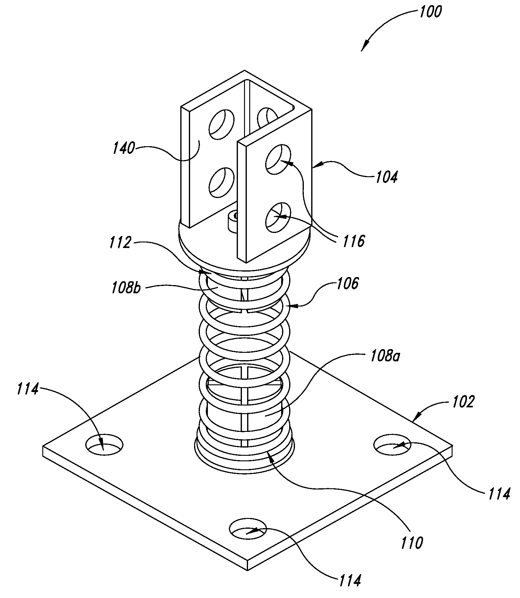
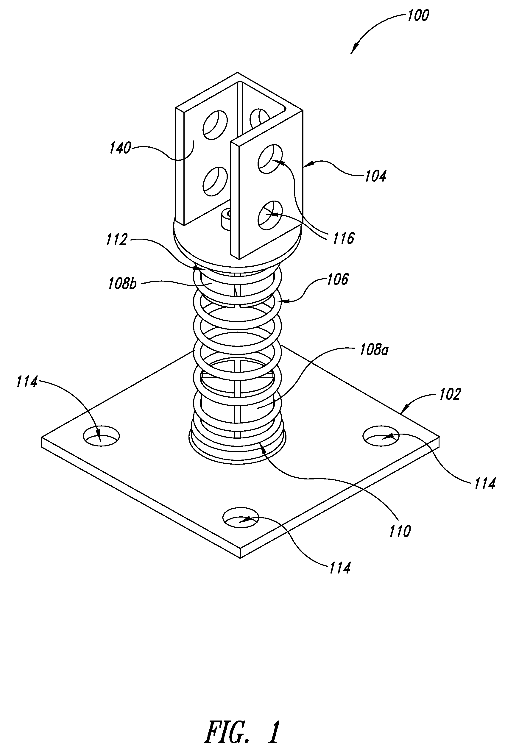
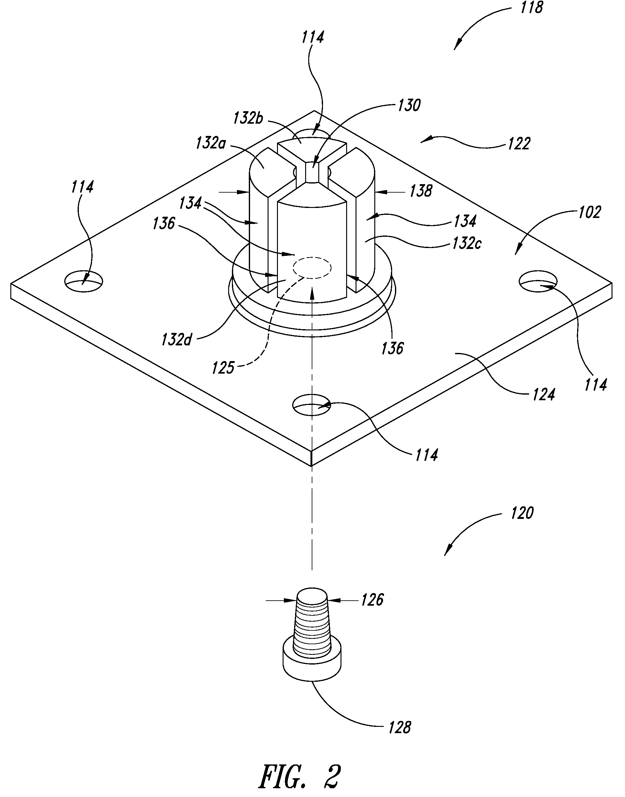
The patent describes an antenna mount that uses a resilient member to temporarily deform and release the antenna from the base in response to a force applied to the mounting member. This allows for a secure and easy way to mount an antenna to an object carrying the base. The technical effects of this invention include improved stability and ease of use for mounting antennas to various objects.

Problems solved by technology

While potentially enhancing reception, such exposure subjects the antenna and / or readers to possible damage.
For example, forklifts and tugs often operate in highly confined spaces.
Such may cause a vehicle mounted antenna and / or reader to be torn from the vehicle.
Such may cause a portal, wall, pillar or other support structure mounted antenna and / or reader to be torn from the support structure.
RFID systems are typically very costly.
Damaged elements are not only costly to replace, but replacement may take time, adversely effecting the entities operations.

Method used


Image

  • Frangible antenna mount
  • Frangible antenna mount
  • Frangible antenna mount

Examples


Embodiment Construction

[0020]In the following description, certain specific details are set forth in order to provide a thorough understanding of various disclosed embodiments. However, one skilled in the relevant art will recognize that embodiments may be practiced without one or more of these specific details, or with other methods, components, materials, etc. In other instances, well-known structures associated with systems and methods for mounting objects such as antennas have not been shown or described in detail to avoid unnecessarily obscuring descriptions of the embodiments.

[0021]Unless the context requires otherwise, throughout the specification and claims which follow, the word “comprise” and variations thereof, such as “comprises” and “comprising” are to be construed in an open, inclusive sense, that is as “including, but not limited to.”

[0022]Reference throughout this specification to “one embodiment” or “an embodiment” means that a particular feature, structure or characteristic described in ...


PUM


Abstract

An antenna mount includes a base, a mounting member and a resilient member extending between the mounting member and the base. The resilient member may be removably coupled to the base via a first coupling member and / or coupled to the antenna mount via a second coupling member. The coupling members and the resilient member are configured to release or disengage in response to a force and / or torque exceeding a threshold force and / or torque.

Description

BACKGROUND OF THE INVENTION[0001]1. Field of the Invention[0002]The present disclosure generally relates to support mounts, and more particularly, but not exclusively, to a frangible mount for supporting automatic data collection (ADC) equipment, for example an antenna to transmit and / or read information stored in a Radio Frequency Identification (RFID) device.[0003]2. Description of the Related Art[0004]Businesses, governments and other entities are increasingly using ADC devices to automate the handling of items such as packages, goods, animals and people. ADC systems typically employ one or more readers that are operated to read information from one or more data carriers. For example, one type of ADC system employs one or more machine-readable symbol readers to optically read information from machine-readable symbols (e.g., barcode symbols, stack code symbols, area or matrix code symbols). Another type of ADC system employs one or more RFID readers or interrogators to wirelessly ...

Claims


Application Information

Patent Timeline
Patent Type & Authority Patents(United States)
IPC IPC(8): H01Q1/12
CPCH01Q1/085H01Q1/1207H01Q1/32
Inventor HAYNES, CLARKEBY, ADAM
Owner INTERMEC IP CORP
Features
  • R&D
  • Intellectual Property
  • Life Sciences
  • Materials
  • Tech Scout
  • Unparalleled Data Quality
  • Higher Quality Content
  • 60% Fewer Hallucinations
Learn More