Supercharge Your Innovation With Domain-Expert AI Agents!

Safety system

a safety system and safety technology, applied in the field of safety systems, can solve the problems of operator injury, operator difficulty in performing the most efficient manner, and operator difficulty in holding and manipulating work,

Active Publication Date: 2008-11-11
DAVIES KEVIN S
View PDF15 Cites 8 Cited by
  • Summary
  • Abstract
  • Description
  • Claims
  • Application Information

AI Technical Summary

Problems solved by technology

Such action by the operator obviously has the potential to cause serious injury to the operator, given the force applied by the tool and the speed at which it can move.
The use of physical safety guards however can obstruct the view of the operator during use and impede access to the work making it difficult for the operator to perform their job in the most efficient manner.
The use of tethers however also makes holding and manipulation of the work difficult and therefore decreases the efficiency with which the operator can work.
These arrangements of individual light beams also have disadvantages in that the operator is kept away from the work area.
Further the use of individual light beams also results in small gaps in the light curtain, into which small objects such as fingers can be placed without triggering deactivation of the machine.
Known problems with these types of arrangements include the need to re-align the light beams when tools are changed and the possibility that an operator may move their hand under the tool just as the beams are deactivated.

Method used


Image

  • Safety system
  • Safety system
  • Safety system

Examples


Embodiment Construction

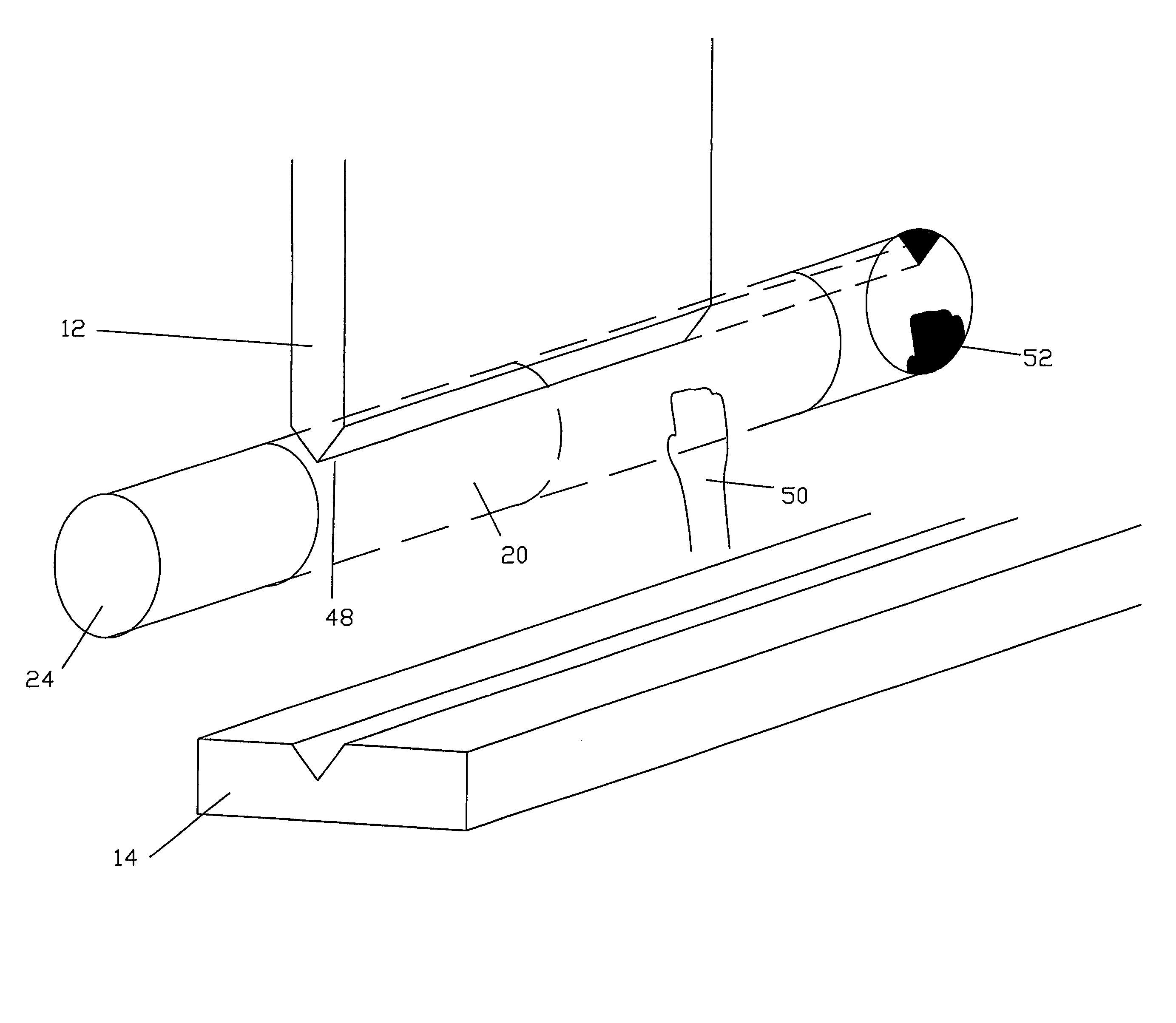
[0025]Referring to the Figures, there is shown a safety system for use with machinery having moving parts to detect the presence of an obstruction in the path of the moving part. In the embodiment shown, the safety system is employed on a press brake comprising a tool 12 arranged to move relative to an anvil 14 and to strike work placed on the anvil 14. The safety system includes a light emitting means 16 and a light receiving means 18. The light emitting means 16 is arranged to illuminate a region 20 around a portion of the path of movement of the tool 12 in order to detect obstructions in said region 20.

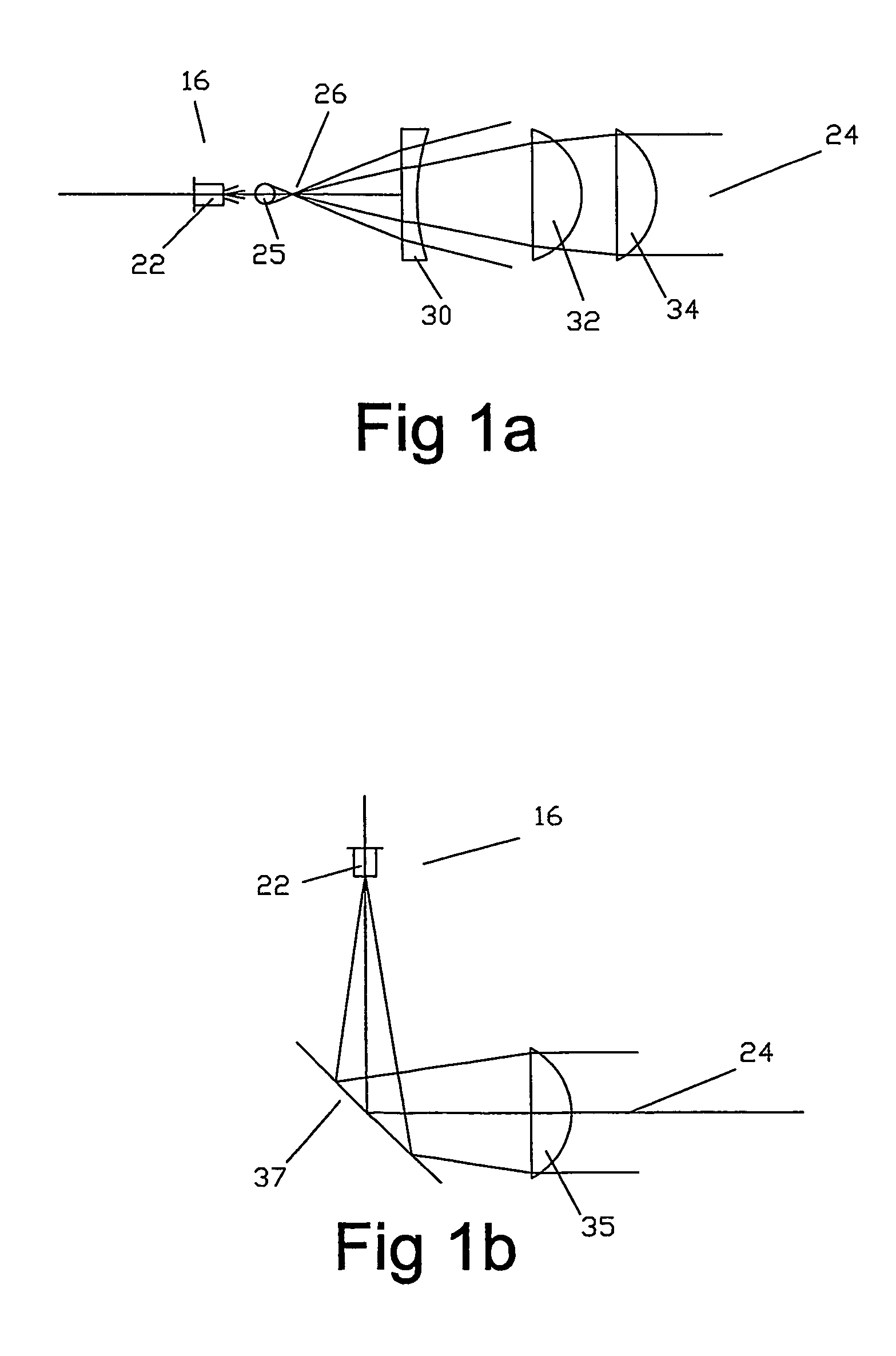
[0026]FIG. 1a shows an arrangement in which a laser diode 22 is used to create a large area parallel light beam 24. In the arrangement shown in FIG. 1a, the laser diode 22 is used to illuminate a spherical ball 25. The spherical ball 25 concentrates the laser beam onto a point 26. The point source of light may be further refined by passing it through a pin hole (not shown), Past th...


PUM

PropertyMeasurementUnit
areaaaaaaaaaaa
speedsaaaaaaaaaa
relative speedsaaaaaaaaaa

Abstract

A safety system for use with a machine having a moving tool arranged to move through a known path of movement. The safety system is arranged to detect the presence of an obstruction in a region (20) around a portion of said path deemed to be hazardous. The safety system is characterised by comprising a light emitting means (16), a light receiving means (18) and a processing and control means. The light emitting means (16) is arranged to emit light generally parallel to the path of movement of the tool such that the region (20) is illuminated. The light receiving means (18) is arranged to receive light from the light emitting means (16) which has passed through the region (20). The processing and control means is arranged to receive information from the light receiving means (18) and determine whether an obstruction exists in the region (20) by the presence of one or more shadow regions cast on the light receiving means (18) by the obstruction and to control movement of the tool (12) dependent on the presence of obstructions in the region (12).

Description

CROSS-REFERENCE TO RELATED APPLICATION[0001]This is the 35 USC 371 National Phase of International Application PCT / AU03 / 00707, filed Jun. 10, 2003, and published as WO03 / 104711.BRIEF DESCRIPTION OF THE INVENTION[0002]The present invention relates to a safety system, in particular a system for use with machinery having moving parts, such as press brakes, to detect the presence of an obstruction in the path of the moving part.FIELD OF THE INVENTION[0003]In the past, various mechanisms have been used to prevent the operators of industrial machinery, such as press brakes, from placing their hands beneath the moving tool during operation. Such action by the operator obviously has the potential to cause serious injury to the operator, given the force applied by the tool and the speed at which it can move.[0004]One such safety mechanism involves the use of physical guards that are placed between the operator and the tool. The use of physical safety guards however can obstruct the view of t...

Claims


Application Information

Patent Timeline
Patent Type & Authority Patents(United States)
IPC IPC(8): B21D55/00B21B37/58B21C51/00F16P3/14B23Q11/00B21D5/02B30B15/00B30B15/28
CPCB30B15/285F16P3/144F16P3/14
Inventor DAVIES, KEVIN S.
Owner DAVIES KEVIN S
Features
  • R&D
  • Intellectual Property
  • Life Sciences
  • Materials
  • Tech Scout
  • Unparalleled Data Quality
  • Higher Quality Content
  • 60% Fewer Hallucinations
Learn More