Linear voltage regulator with improved responses to source transients

a linear voltage regulator and transient technology, applied in the field of linear voltage regulators, can solve the problems of out-of-regulation output voltage and long oscillation period, and achieve the effect of improving the regulation control of output voltag

Active Publication Date: 2008-11-11
GLOBAL MIXED MODE TECH
View PDF9 Cites 24 Cited by
  • Summary
  • Abstract
  • Description
  • Claims
  • Application Information

AI Technical Summary

Benefits of technology

[0007]An object of the present invention is to provide a linear voltage regulator capable of preventing the operation state of the regulating transistor from dramatically changing while an input voltage source makes a transient, thereby improving the regulation control over the output voltage.

Problems solved by technology

Unfortunately, when the input voltage source Vin makes a transient, the regulating transistor 11 changes dramatically in operation, causing the output voltage Vout to be out of regulation and to oscillate for a long period of time.

Method used


Image

  • Linear voltage regulator with improved responses to source transients
  • Linear voltage regulator with improved responses to source transients
  • Linear voltage regulator with improved responses to source transients

Examples


Embodiment Construction

[0017]The preferred embodiments according to the present invention will be described in detail with reference to the drawings.

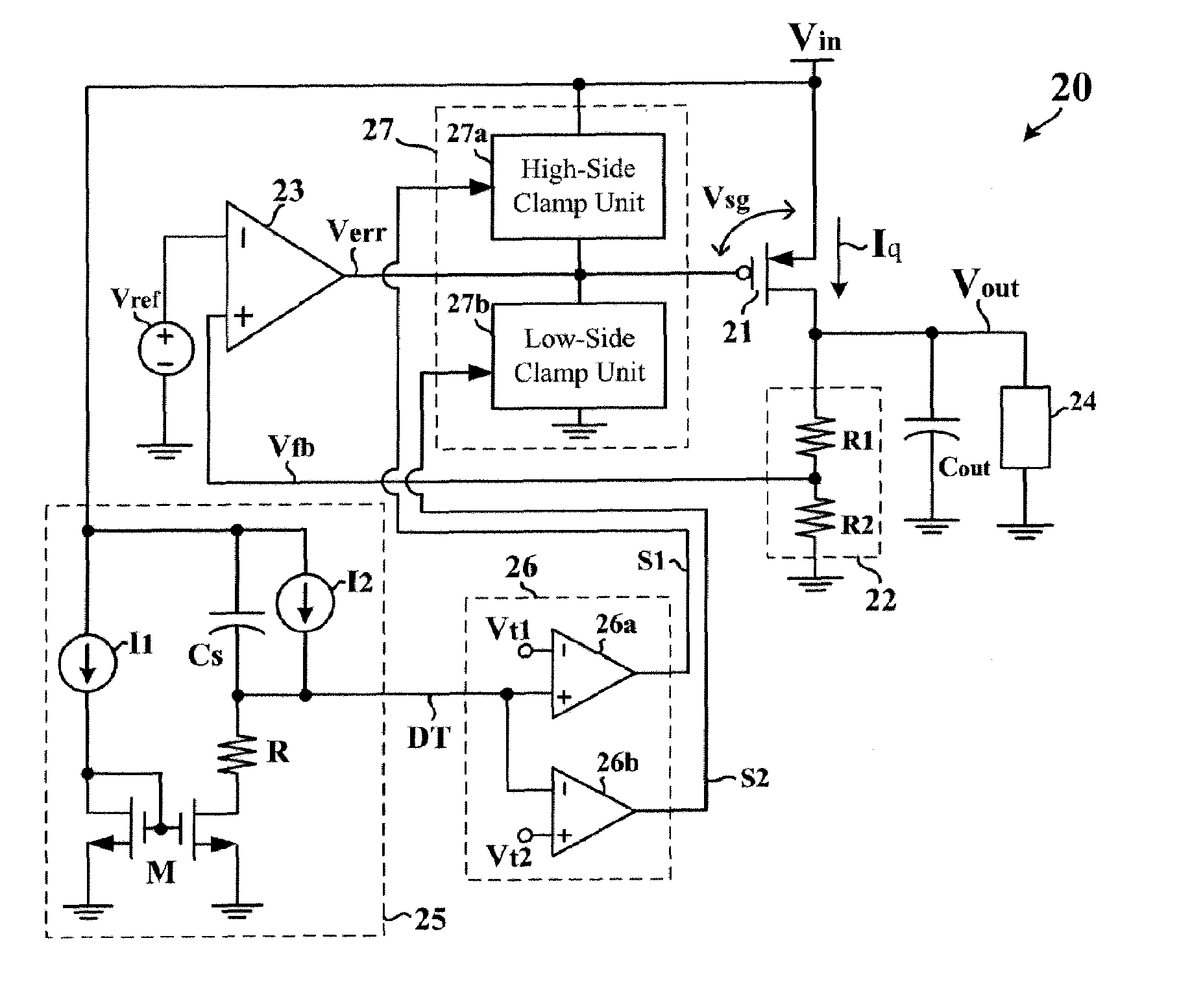
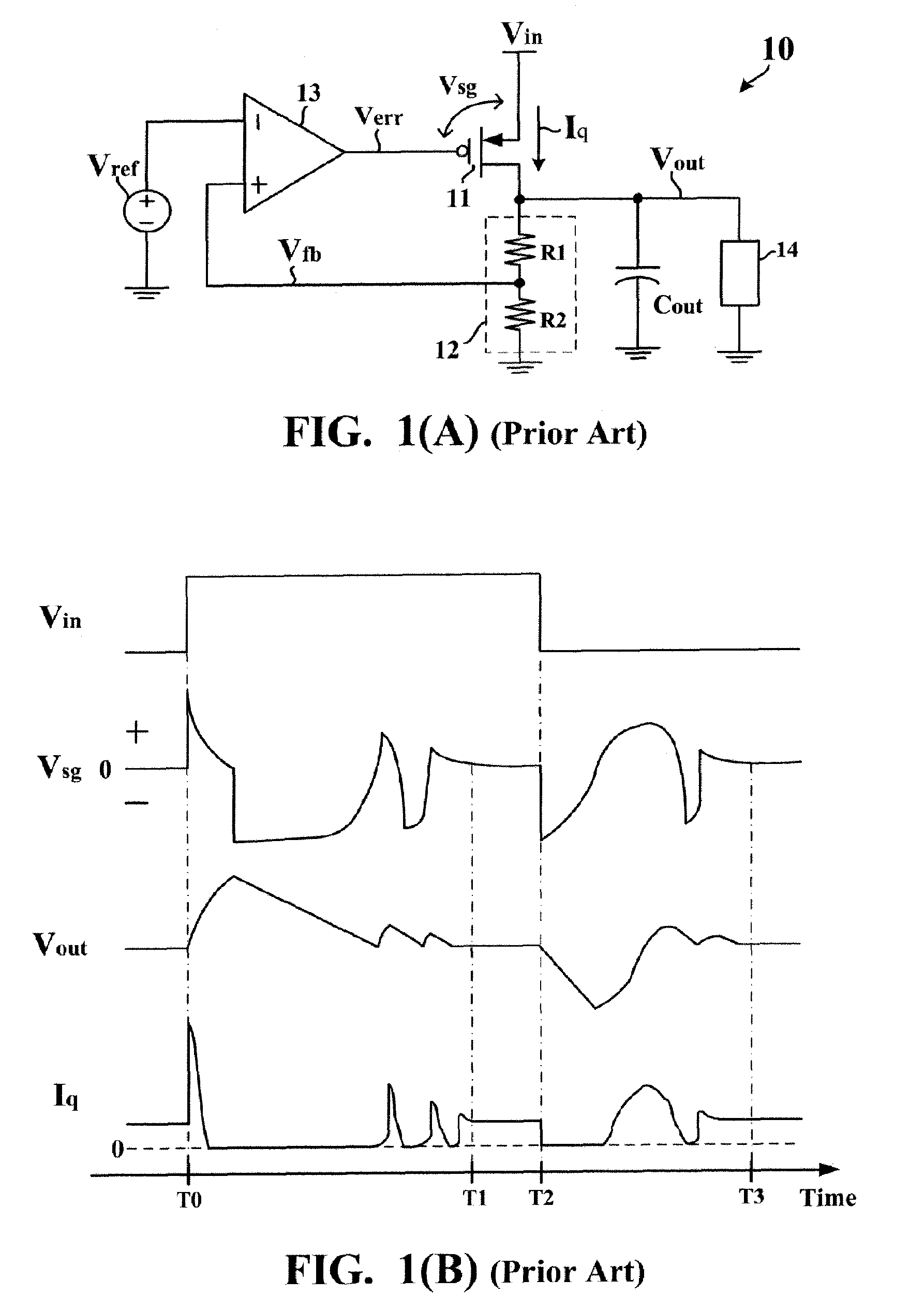
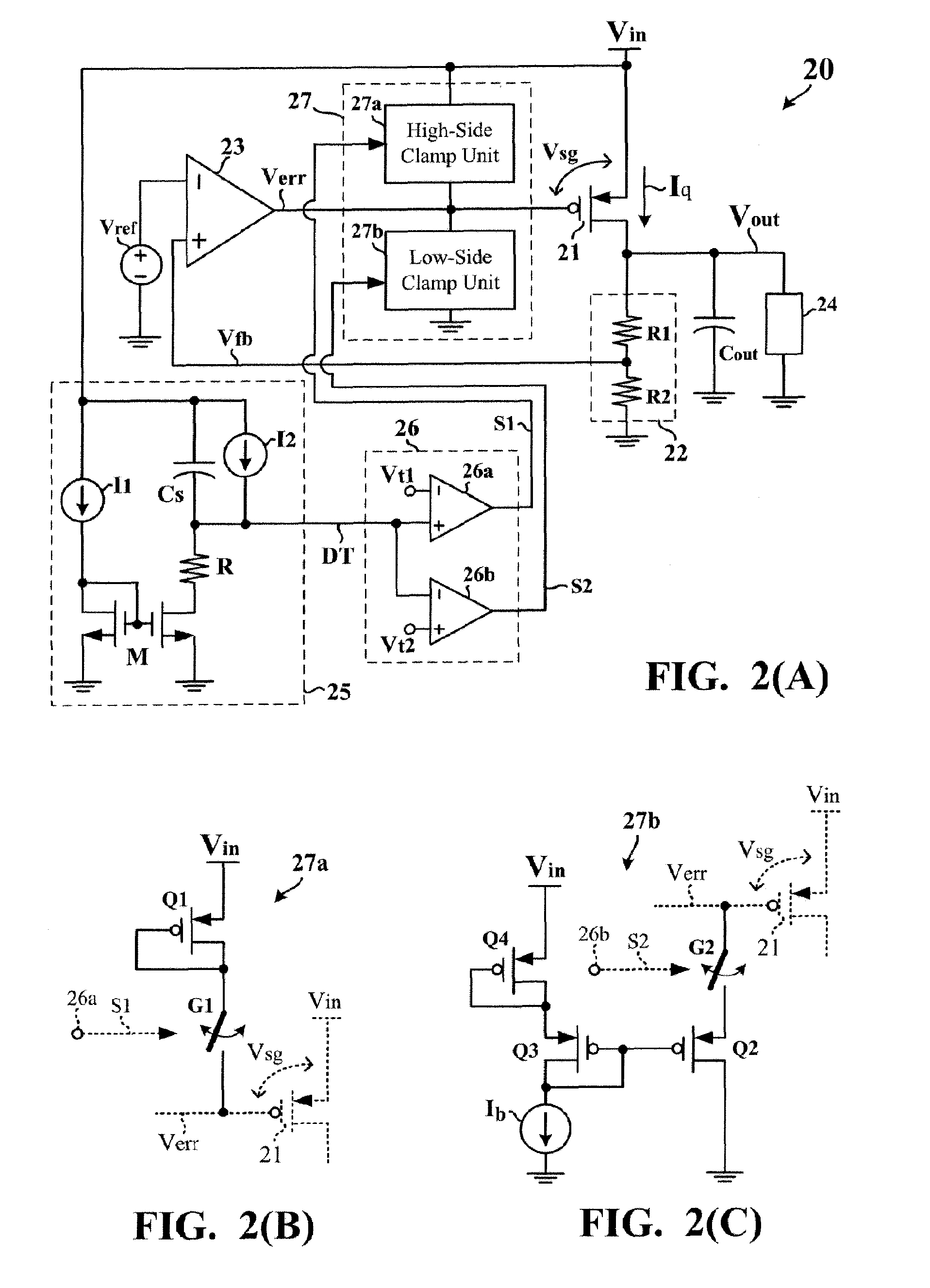
[0018]FIG. 2(A) is a circuit diagram showing a linear voltage regulator 20 according to the present invention. The linear voltage regulator 20 primarily includes a regulating transistor 21, a voltage feedback circuit 22, and an error amplifying circuit 23, all together constituting a feedback control loop. The voltage feedback circuit 22 is typically implemented by a voltage divider of series-connected resistors R1 and R2, for generating a feedback signal Vfb as a representative of an output voltage Vout. Based on comparison between the feedback signal Vfb and a predetermined reference voltage Vref, the error amplifying circuit 23 generates an error signal Verr. Subsequently, the error signal Verr is applied to a control electrode of the regulating transistor 21. Also, the regulator transistor 21 has a first channel electrode receiving an input voltage source...


PUM


Abstract

A linear voltage regulator has a regulating transistor with a first channel electrode receiving an input voltage source and a second electrode providing an output voltage. A control electrode of the regulating transistor is controlled by an error amplifying circuit based on comparison between a feedback signal of the output voltage and a reference voltage. An event detecting circuit is coupled to the input voltage source for detecting occurrence of a transient in the input voltage source. In response to the detected transient event, an enable controlling circuit generates an enable signal for determining an effective operation time of a voltage clamping circuit. During such effective operation time, a potential difference between the first channel electrode and the control electrode is limited within a predetermined clamp voltage for preventing the regulating transistor from being dramatically changed in operation.

Description

BACKGROUND OF THE INVENTION[0001]1. Field of the Invention[0002]The present invention relates to a linear voltage regulator and, more particularly, to a linear voltage regulator capable of effectively controlling an output voltage even while an input voltage source makes a transient.[0003]2. Description of the Prior Art[0004]FIG. 1 is a circuit diagram showing a conventional linear voltage regulator 10. The linear voltage regulator 10 primarily includes a regulating transistor 11, a voltage feedback circuit 12, and an error amplifying circuit 13, all together constituting a feedback control loop. The voltage feedback circuit 12 is typically implemented by a voltage divider of series-connected resistors R1 and R2, for generating a feedback signal Vfb as a representative of an output voltage Vout. Based on comparison between the feedback signal Vfb and a predetermined reference voltage Vref, the error amplifying circuit 13 generates an error signal Verr. Subsequently, the error signal...

Claims


Application Information

Patent Timeline
Patent Type & Authority Patents(United States)
IPC IPC(8): H02H7/00H02H9/00H02H3/22
CPCG05F1/575
Inventor TAIN, YA-DERCHEN, YUNG-CHIH
Owner GLOBAL MIXED MODE TECH
Why Eureka
Try Eureka