Guiding rail for a cabinet pull-out part

a technology for pulling out parts and guiding rails, which is applied in the direction of drawers, furniture parts, domestic applications, etc., and can solve the problem that the blocking device may also be released

Inactive Publication Date: 2008-11-18
PAUL HETTICH
View PDF4 Cites 13 Cited by
  • Summary
  • Abstract
  • Description
  • Claims
  • Application Information

AI Technical Summary

Benefits of technology

[0011]As a result, it is one aspect of the present invention to provide a guiding rail of the above-mentioned type where a blocking device can be unlocked in both displacement directions without any significant expenditure of force and without the risk that the blocking device can be triggered by involuntary or faulty operations.
[0014]When the guiding rail is to be extended from its pushed-together state or is to be collapsed from its extended state, an operation of the rod with the at least one snap-in tooth is necessary in both cases. Operation of the rod with the at least one snap-in tooth moves the at least one snap-in tooth either out of the recess of the carcass rail or swivels the at least one snap-in tooth out of the face side area of the center rail. In either case, once the snap-in tooth has been disengaged from the corresponding locking structure, movement of the guiding rail becomes possible. After disengagement of the at least one snap-in tooth, for the longitudinal displacement of the guiding rail, in the pull-out direction as well as in the push-in direction, only the internal frictional forces have to be overcome, but no additional forces have to be applied for eliminating the blocking.

Problems solved by technology

However, particularly when the drawer is fully open, in the case of previous constructions, the blocking device may also be released by an unintended pushing against the drawer part.

Method used


Image

  • Guiding rail for a cabinet pull-out part
  • Guiding rail for a cabinet pull-out part
  • Guiding rail for a cabinet pull-out part

Examples


Embodiment Construction

[0026]While the present disclosure describes embodiment(s) of the invention, the scope is intended to encompass variations and equivalents thereof, as would be appreciated by those skilled in the art.

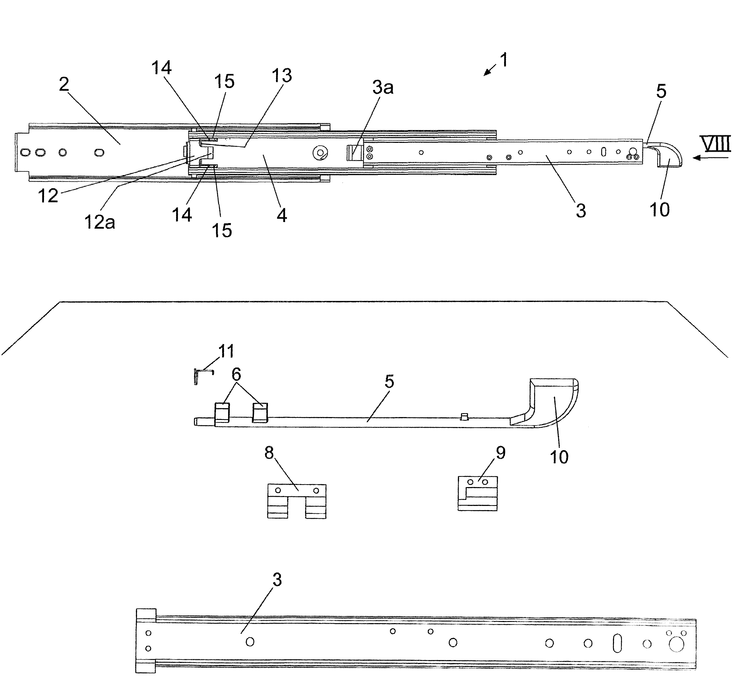
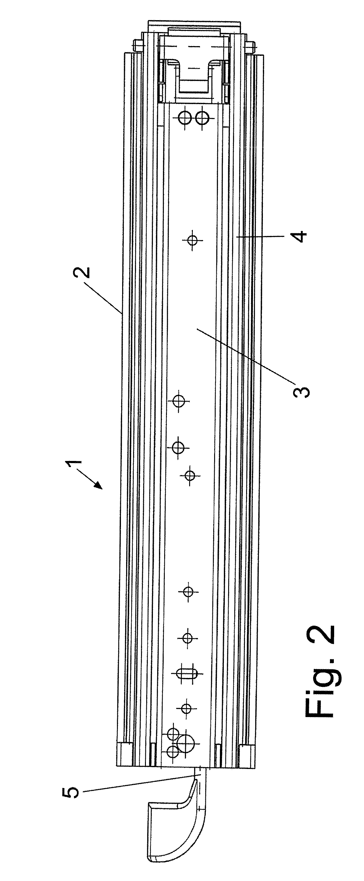
[0027]In the drawings, reference number 1 indicates a guiding rail for a cabinet drawer part, which is not shown. The cabinet drawer part may be a drawer, shelf, or other structure suitable for supporting or containing one or more predetermined articles thereon or therein. As illustrated in FIG. 2, the guiding rail 1 includes a carcass rail 2 fixable to a cabinet carcass, a running rail 3 connectable with a drawer part, and a drawer-extending center rail 4 arranged between the carcass rail 2 and the running rail 3. The running rail 3 is telescopically slidable within the center rail 4, which is telescopically slidable within the carcass rail 2. This telescopic arrangement is illustrated, for example, in FIG. 6.

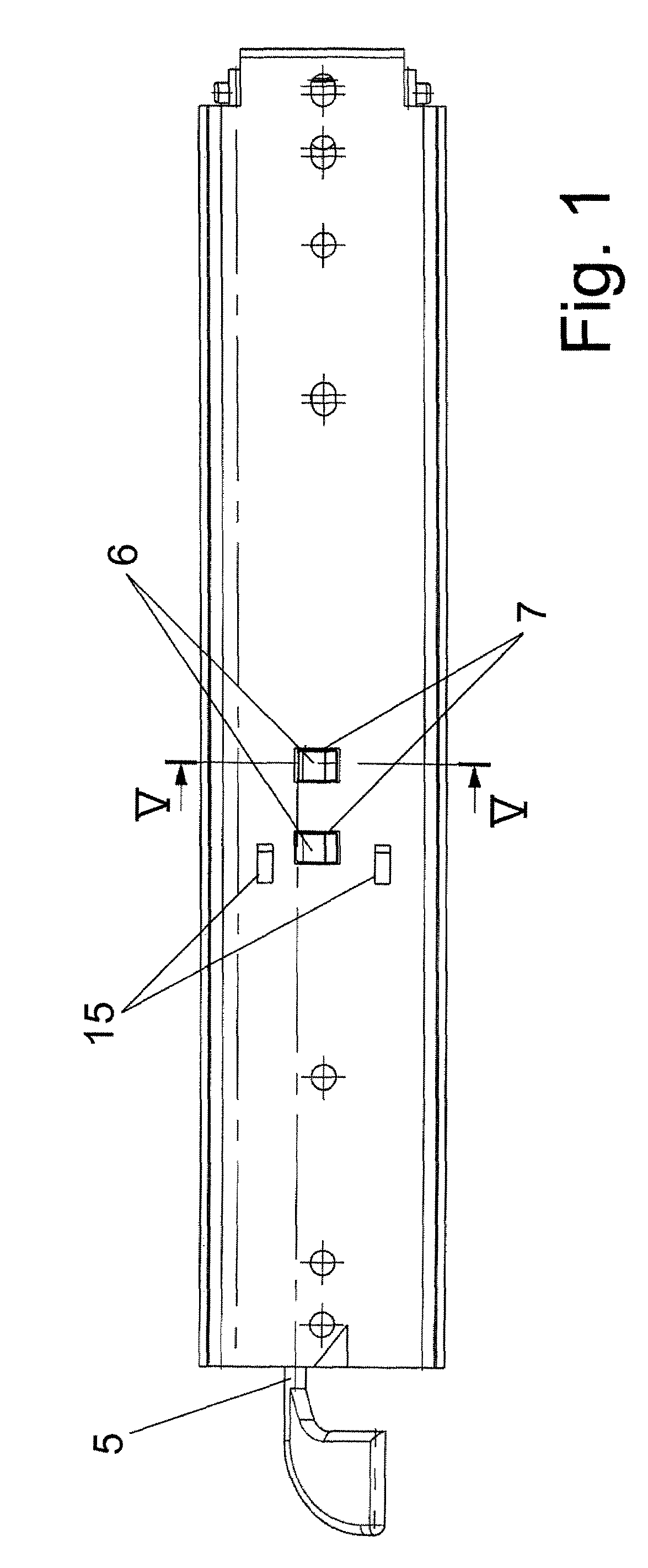
[0028]In the fully pushed-together condition, as shown in FIGS. 1 to 4, the g...


PUM


Abstract

A guiding rail is described with a carcass rail, fixable to a cabinet carcass, a running rail, fixable to the cabinet pull-out part, a center rail slidably connecting the carcass rail to the running rail, permitting telescopic movement of the carcass rail, the center rail, and the running rail with respect to one another from a compressed position to an extended position, a blocking device, and an operating lug disposed in a rearward end of the running rail. The blocking device includes a rod, at least one first snap-in tooth projecting from the rod, a notch lever pivotally disposed at a rearward end of the center rail, and at least one second snap-in tooth associated with the notch lever. The first and second snap-in teeth engage associated components of the guiding rail such that the guiding rail is lockable in both the extended and compressed positions.

Description

CROSS-REFERENCE TO RELATED APPLICATIONS[0001]This application is a first-filed application and, therefore, does not rely on any other application for priority.BACKGROUND[0002]1. Field of the Invention[0003]The present invention relates to a guiding rail for a cabinet pull-out part, such as a drawer. More specifically, the present invention relates to a cabinet pull-out part with a carcass rail, which can be fixed to a cabinet carcass, a running rail, which can be fixed to the drawer part, and a pull-out, extending, center rail arranged between the carcass rail and the running rail. Even more specifically, the present invention relates to a cabinet pull-out part including a blocking device where the guiding rail can be mechanically locked in the completely pushed-together state as well as in the fully extended state.[0004]2. Related Art[0005]Guiding rails are known per se.[0006]Particularly, when such guiding rails are used in the case of heavy drawer parts and / or when corresponding ...

Claims


Application Information

Patent Timeline
Patent Type & Authority Patents(United States)
IPC IPC(8): A47B88/04A47B88/49A47B88/493
CPCA47B88/08A47B88/10A47B2210/0089A47B2210/0016A47B88/49A47B88/493A47B88/53
Inventor BURGESS, III, THOMAS EDWARD
Owner PAUL HETTICH
Why Eureka
Try Eureka